
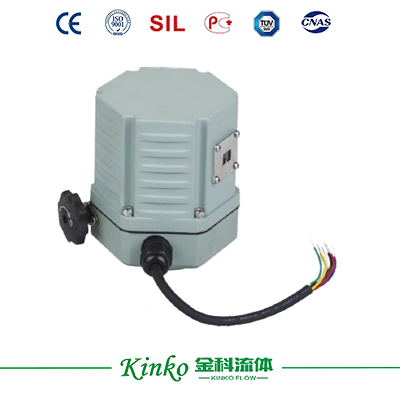
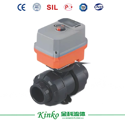
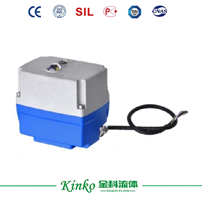
KK-02K low-torque electric actuator provides 15Nm output with wide AC85-260V and DC24V compatibility. IP67-rated housing and 50dB low noise suit small-diameter ball, butterfly and plastic valves.
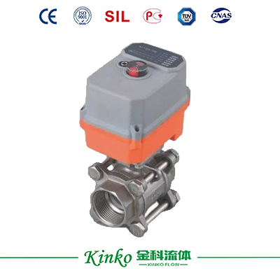
KK-02K low-torque electric actuator provides 15Nm output with wide AC85-260V and DC24V compatibility. IP67-rated housing and 50dB low noise suit small-diameter ball, butterfly and plastic valves.
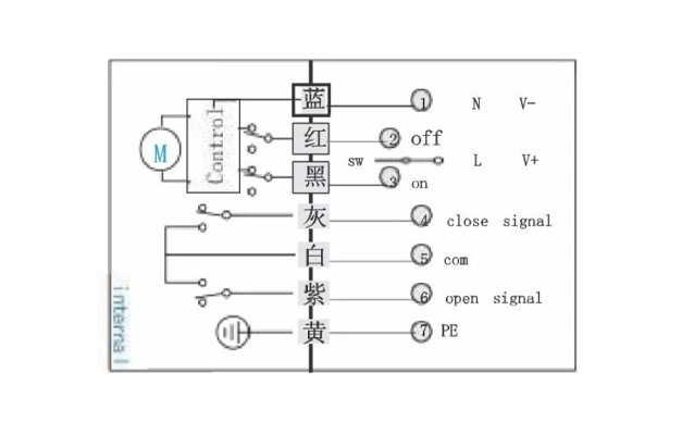
Wiring instructions
Strictly follow the color wiring; incorrect wiring will cause damage to the actuator.
The actuator is equipped with a quick plug. Please correctly match the male and female plug positioning slots and tighten the female plug
Feedback signal contact camying capacity, 0.1A/250YAC; 0.5A/30YDC"
Two or more actuators cannot be used in parallel under the same control contact
Control instructions:
When the SW switches to red, the actuator rotates clockwise and automatically stops when it is in place, and the white and purple colors are connected, giving a signal for the closing contact.
When the SW switches to black, the actuator rotates counterclockwise, and when it is in place, the actuator stops moving in white, and the white and gray are connected, giving an open contact signal.
During operation, white, gray, and purple are in an open-circuit state."
The contact signal will be slightly earlier than the actual arrival time, so the power cannot be cut off when the contact signal is detected.

| Electrical parameters | Working Voltage | DC24V, AC24V, AC85-260V |
| Power consumption | 85W@ Run 0.25W@ Keep | |
| Peak current | 4A@5ms @Rated volitag | |
| Electrical interface | 7×0.35mm² cable, withstand voltage AC300V | |
| Fuse specifications | 10A | |
| Rated torque | 15N·m @rated voltage | |
| Functional Parameters | Rotation angle | 90±2° |
| Maximum rotation angle | 360° | |
| Manual operation | ※Comes with a hexagonal wrench for use in the event of a power outage | |
| Operating time | About seconds | |
| Operating frequency | Non-continuous operation cycle≥1 minute | |
| Noise level | Maximum 50dB(A) | |
| Position Indicator | Mechanical indicator | |
| Working conditions | Electrical grade | ClassⅢ (Safe Low Voltage) |
| Flame retardant rating | 1.6mmHB / UL94 testing method | |
| Protection rating | IP67 As Per En60529/GB4208-2008(all directions) | |
| Insulation resistance | 100MΩ/500V DC | |
| Pressure Rating | 500VAC for 1 minute | |
| Temperature of the medium matched with the valve | ≤80℃ can be directly connected to the actuator for installation ※>80℃ requires installation of brackets or heat dissipation devices |
|
| Working environment | Indoor or outdoor, in environments with long-term rain or direct sunlight Protective devices need to be installed to protect the actuator |
|
| Explosion-proof rating | Non-explosion-proof products should not be installed in flammable and explosive environments | |
| Ambient temperature | - 20℃~60℃ (ABS) | |
| Non-working temperature | ※≤-40℃ or≥80℃ | |
| Ambient humidity | 5-95% RH relative humidity, no condensation | |
| Impact | ≤300m/S² | |
| Specification size/weight | Vibration | ※ 10 to 55 Hz, 1.5mm dual amplitude |
| Installation Method | 360°arbitrary angle, manual operation, or wiring space needs to be reserved | |
| Maintenance | Maintenance-free | |
| Certificate Type | ||
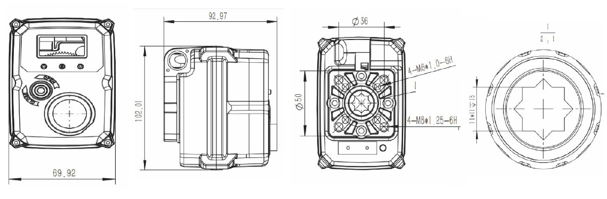
| Size (L×W×H) | See Specification and Dimensions | |
| Connection standards | ISO5211 F03, F04, F05 | |
| Output shaft specifications | Inner Eight Directions | |
| Hole depth/shaft length | < 15 mm (Inner Eight Directions) | |
| Weight | 1kg |
| Valve body type | Recommended assembly conditions |
| Wafer type butterfly Valve | Meet the requirement of actuator torque > 2 times the max. Torque of the valve |
| Flanged butterfly Valve | Meet the requirement of actuator torque > 1.7 times the max. Torque of the valve |
| Metal ball Valve | Meet the requirement of actuator torque > 1.7 times the max. Torque of the valve |
| Plastic ball Valve | Meet the requirement of actuator torque > 1.5 times the max. Torque of the valve |
1. If the ball valve does not operate for a long time, the maximum torque value for the first opening or closing of the valve is the maximum torque.
2. When installing the direct connection type, if the hole depth is ≤ 15 mm and the output shaft of the valve is> 15 mm, it needs to be cut.
3. If you need to provide your own bracket and coupling, please pay attention to the following:
4. Screws should be equipped with spring washers and flat washers. It is recommended to apply sealant around the screw after tightening to prevent loosening.
5. After installation, the device should be turned on and off once using the handle drive, and after confirming that it is working properly, the valve adjustment steps should be executed.

Lorem ipsum dolor sit amet, consectetur adipiscing elit. Aenean euismod bibendum laoreet. Proin gravida dolor sit amet lacus accumsan et viverra justo commodo. Proin sodales pulvinar sic tempor. Sociis natoque penatibus et magnis dis parturient montes, nascetur ridiculus mus. Nam fermentum, nulla luctus pharetra vulputate, felis tellus mollis orci, sed rhoncus pronin sapien nunc accuan eget.

Fields marked with * are required.