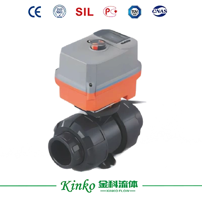
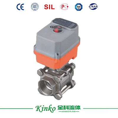
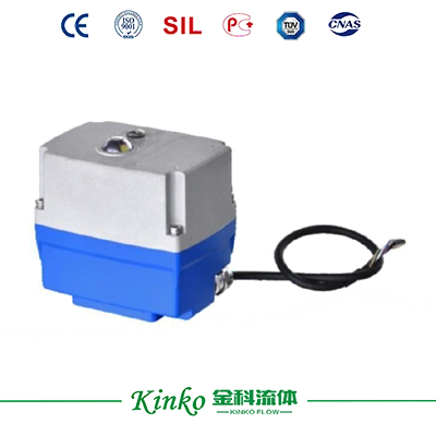
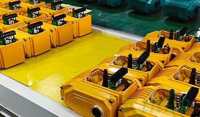
Electric Actuator

Electric Actuator

Adopting a 1.3-inch OLED large-screen LCD with no viewing-angle limitation, high brightness, energy saving, and environmental protection, real-time display of valve opening and external control commands, automatically entering sleep mode after about 5 minutes, and prompting position status and control commands during sleep.


Get a Quote
Download Drawings

    Product Overview

    • Unique non-opening interactive two-step valve mode:

    Step 1: Control the valve to the "closed calibration" position through the button and save it;

    Step 2: Control the valve to the "open calibration" position through the button and save it; Easily complete valve adjustment. Thoroughly solves the tedious and inconvenient _adjustment of the mechanical positioning switch valve position.

    • Adopting a32-bit high-performance CPU, a 12-bit high-precision AD conversion chip, and a built-in unique algorithm, it completely eliminates mechanical hysteresis and greatly reduces control errors in valve position Poor.

    • Built-in motor control module, capable of variable frequency speed control of the motor, achieving precise positioning.

    • Adopting non-contact positioning, modular design of the control unit, and encapsulation treatment ensures the reliable operation of the components, greatly improving the service life of the product; The interface adopts standard connectors, which are easy to install, debug, and replace.

    • Real-time fault menu prompt (including faults caused by actuator jamming or other reasons resulting in the actuator switch not being in place), and can output fault alarm signals.

    • The exchange of valve control commands can be achieved through the menu.

    • Remote control and on-site control can be automatically switched through the menu, and valve position can be adjusted arbitrarily through buttons. It has built-in electronic limits and prompts the limit status.

    • Through the menu, the valve closing position can be shifted towards the valve opening or closing direction, greatly reducing the complexity and inconvenience of on-site adjustment caused by "ordinary switch-type mechanical positioning".

    • The system can restore factory settings through key operations.

     

    Specifications

    Product Overview


    Working voltage AC220V (AC85V-260V), AC/DC24V
    Rated torque 30 N·m
    Running time Approximately 15 seconds
    Control mode 4-20mA 0-20mA 0-5V 1-5V 0-10V 2-10V, (optional fault alarm+A)
    Feedback method 4-20mA 0-20mA 0-5V 1-5V0-10V 2-10V
    Position accuracy ± 1% (software adjustable)
    Adopting a high-performance brushless motor with built-in overcurrent and overload protection


    Technical Parameters


    Electrical parameters Rated Voltage AC230V (50/60HZ) AC/DC24V
    Working voltage range AC85-260V/DC100-300V
    Power consumption @rated voltage 9.6W @run 0.12Whold 9.6W @run 085W hold
    Peak current @rated voltage 35mA @5ms @AC230V 350mA @5ms @DC24V
    75mA @5ms @AC110V
    Fuse specifications 1A 2A
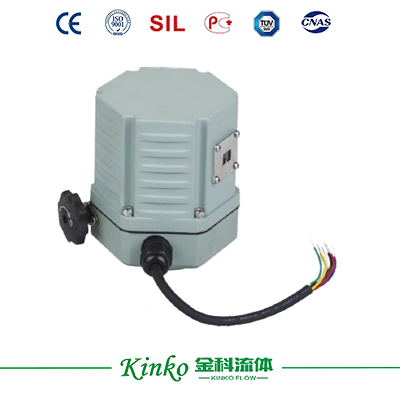
    Electrical interface 7×0.2mm²cable, withstand voltage AC300V(wire length 800mm)
    Functional Parameters Rated torque 20N.m @rated voltage
    Rotation angle 90±2°
    Max. rotation angle 360°
    Manual operation ※Comes with a hexagonal wrench for use in the event of a power outage
    Operating time About 10 seconds
    Operating frequency Non-continuous operation cycle≥1 minute
    Noise level Maximum 50dB(A)
    Position Indicator Mechanical indicator
    Working conditions Electrical grade Class Ⅰ (Grounding Protection) Class Ⅲ(Safe Low Voltage)
    Flame retardant rating 1.6mmHB/UL94 testing method
    Protection rating IP67 As Per En60529/GB4208-2008 (all directions)
    F-type can be equipped with a dehumidification heater
    Insulation resistance 100MΩ/1500VDC 100M/500VDC
    Pressure Rating 1500VAC @1 minute 500VAC @1 minute
    阀门配套的介质温度
    Temperature of the medium matched with the valve
    ≤80℃可与执行器直联安装
    ≤80℃ can be directly connected to the actuator for installation
    Working environment ※>80℃ requires installation of brackets or heat dissipation devices
    ※Indoor or outdoor, in environments with long-term rain or direct sunlight
    Protective devices need to be installed to protect the actuator
    Explosion-proof rating Non-explosion-proof products should not be installed in flammable and explosive environments
    Ambient temperature -20℃-60℃(ABS/-20℃-80℃(压铸铝die cast aluminum)
    Non-working temperature ※≤-40℃ or≥80℃
    Ambient humidity 5-95%RH relative humidity, no condensation
    Impact ≤300m/S²
    Vibration ※10 to 55 Hz,1.5 mm(双振幅dual amplitude)
    Installation Method 360°arbitrary angle, manual operation, or wiring space needs to be reserved
    Maintenance Maintenance-free
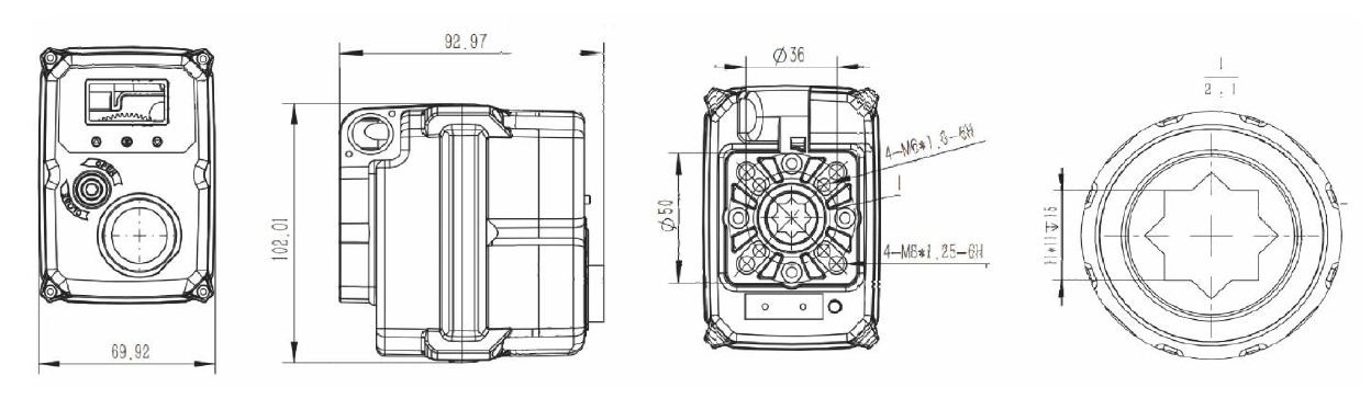
    Specification size/weight Size (L×W×H) See "Specification and Dimensions"
    Connection standards ISO5211 F03, F04, F05
    Output shaft specifications Eight inside or four outside directions
    Hole depth/shaft length < 15 mm (inner octagon)
    Weight ABS material 0.8kg aluminum shell 1kg


    Dimension Drawing


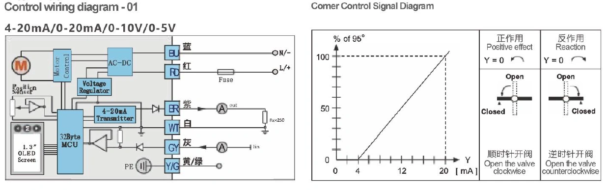
    Control instructions - (No fault signal output -7-core wire)

    1. Confirm the operating voltage and control signal before use, otherwise it may cause damage to the control module. (Parameter table attached to the side of the actuator)

    2. Blue and red are the power supply terminals.

    3. Purple, white, and gray are control feedback terminals. These three wires must not be connected to the power supply, otherwise it may cause damage to the control module.

    4. Gray is the control signal+: 4-20mA, 0-20mA, 0-10V, 0-5V, etc. The input impedance refers to the corresponding wiring diagram.

    5. Purple is the feedback signal+: 4-20mA, 0-20MA, 0-10V, 0-5V, etc.

    6. White is the common signal for control and feedback-

    7. 4-20mA, 1-10V, 1-5V can be set through "user settings" to disconnect the signal valve and perform actions such as fully open, fully closed, hold, and special positions.

    Downloads

    PDF file icon
    KINKO Electric Series

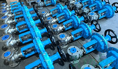
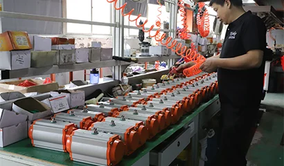
    Application & Case

    Lorem ipsum dolor sit amet, consectetur adipiscing elit. Aenean euismod bibendum laoreet. Proin gravida dolor sit amet lacus accumsan et viverra justo commodo. Proin sodales pulvinar sic tempor. Sociis natoque penatibus et magnis dis parturient montes, nascetur ridiculus mus. Nam fermentum, nulla luctus pharetra vulputate, felis tellus mollis orci, sed rhoncus pronin sapien nunc accuan eget.

    Discover Our Precision Cleaning Solutions Arrow icon
    Industrial application case study

    Related Recommended Products

    Discover Our Range of Products Built for Your Industry's Challenges
    Contact Us

    Get Technical Support or a Customized Solution

    Do our standard products not meet your needs? Share your operating parameters with us, and the Jinke technical team will provide you with personalized selection recommendations and a customized solution.
    Contact experts
    News & Blog
    The Working Principle of The Regulating Valve
    The Working Principle of The Regulating Valve
    The regulating valve is a key piece of equipment used to accurately control the flow of fluids (gas, liquids, or steam) ...
    2026.09.03
    Learn more
    How to install a straight stroke pneumatic actuator?
    How to install a straight stroke pneumatic actuator?
    The installation of straight-stroke pneumatic actuators should follow strict steps and precautions to ensure their effic...
    2026.08.12
    Learn more
    Introduction To The Stroke and Control Mode of Electric Actuators
    Introduction To The Stroke and Control Mode of Electric Actuators
    According to the movement form, the electric actuator can be divided into straight stroke, angular stroke and multi-turn...
    2026.08.05
    Learn more
    onlineCONTACT
    We value your privacy
    We use cookies to provide you with a better online experience, analyse and measure website usage, and assist in our marketing efforts.
    Accept All
    Don't Accept