
Suitable for higher working temperatures and pressures
The connection of the control medium can rotate 360 degrees
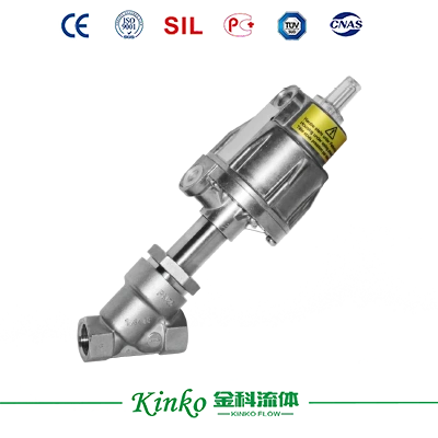
Suitable for higher working temperatures and pressures
The connection of the control medium can rotate 360 degrees
Structure
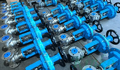
The GEM ü514 series pneumatic metal two-way angle seat valve is equipped with a low maintenance aluminum metal pneumatic actuator. The valve stem seal adopts a self-adjusting design, which has a low maintenance rate and can maintain good sealing performance after long-term operation. The top of the valve stem seal is protected by a cleaning ring to prevent contamination and damage.
Advantages
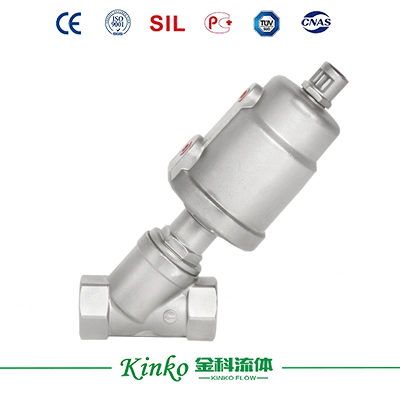
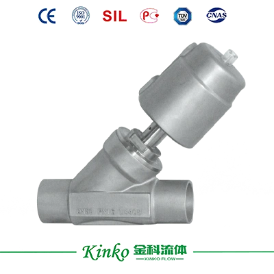
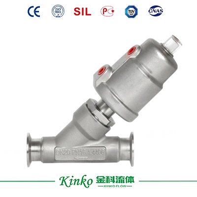
Multiple valve body connection methods are available:
Internal thread, welded connection, clamp connection, flange connection
The angled design ensures good fluid characteristics:
Can adapt to various accessories
Please inquire separately about special connection methods, special seals, and special materials
Optional for food-grade safety requirements, in compliance with Regulation (EC) No 1935/200
(K code 1935) standard gland packing, suitable for vacuum environments up to 20 mbar (a)

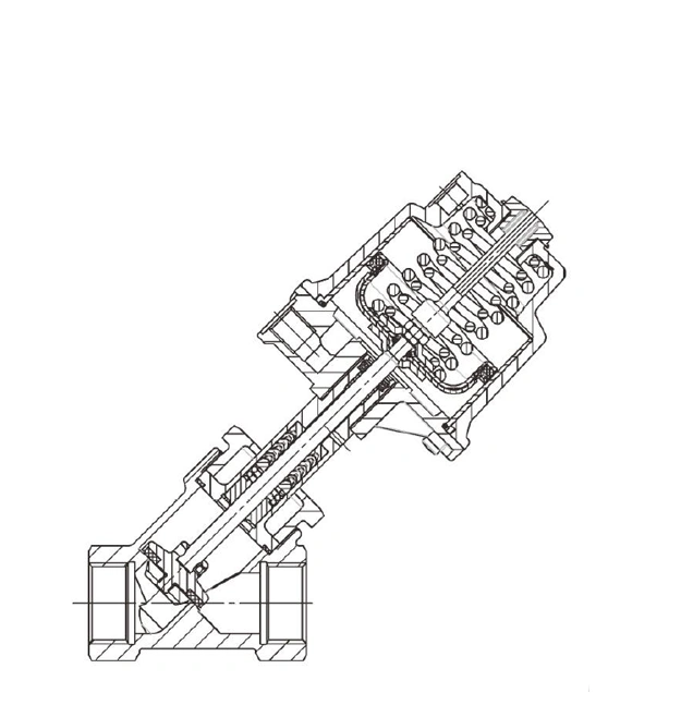
| Working medium | |
| Corrosive or inert gases and fluids that do not undergo any physical or chemical reactions with the valve body and sealing materials. | |
| Max. allowable working medium pressure | See table |
| Medium temperature | -10℃~180℃ |
| Max. allowable viscosity | 600mm2/s(cSt) |
| For specifications suitable for lower or higher temperatures and higher viscosity, please inquire separately. | |
| Control medium | ||
| Noble gas | ||
| Max. allowable control medium temperature | 60℃ | |
| Fill capacity | Pneumatic head | 0: 0.05dm³ |
| Pneumatic heads 1 and 4 | 0.125dm³ | |
| Pneumatic head 2 | 0.625dm³ | |
| Environmental conditions | |
| Ambient temperature | Maximum 60℃ |
| Valve seat | Standard | Test program | leakage rate | Test medium |
| PTFE | DIN EN 12266-1 | P12 | A | Air |
| Nominal inner diameter | Maximum working pressure (bar) Normally closed |
Control pressure (bar) Normally closed |
Kv value | ||||||
| DN | Pneumatic head 0 piston Φ50mm |
Pneumatic head 1 piston Φ70mm |
Pneumatic head 4 piston Φ70mm |
Pneumatic head 2 piston Φ70mm |
Pneumatic head 0 | Pneumatic head 1 | Pneumatic head 4 | Pneumatic head 2 | (m3/h) |
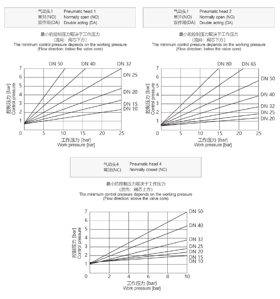
| 15 | 12.0 | 25.0 | 10 | - | 4.7-10 | 5.5-10 | The minimum control pressure is shown in the chart. Maximum control pressure: 7 bar |
- | 5.4 |
| 20 | 6.0 | 20.0 | 10 | 25 | 4.7-10 | 5.5-10 | 4.0-8 | 10.0 | |
| 25 | 2.5 | 10.0 | 10 | 25 | 4.7-10 | 5.5-10 | 4.0-8 | 15.2 | |
| 32 | - | 7.0 | 10 | 22 | - | 5.5-10 | 4.0-8 | 23.0 | |
| 40 | - | 4.5 | 10 | 12 | - | 5.5-10 | 4.0-8 | 41.0 | |
| 50 | - | 3.0 | 10 | 10 | - | 5.5-10 | 5.5-8 | 68.0 | |
| 65 | - | - | - | 7 | - | 5.5-10 | 5.5-8 | 95.0 | |
| 80 | - | - | - | 5 | - | 5.5-10 | 5.5-8 | 130.0 | |
Suitable for the working pressure of sealing material PTFE(code 5).
(V-value test reference standard DIN EN60534, test conditions: DIN ISO 228 standard internal thread valve body, control mode 1(normally closed), adapted to the maximum execution structure under this diameter, measured values for selection reference.)
| Nominal inner diameter | Max. working pressure (bar) Normally open/double acting |
Control pressure (bar) Normally open/double acting |
||
| DN | Pneumatic head 1 piston Φ70 mm |
Pneumatic head 2 piston Φ120 mm |
Pneumatic head 1 | Pneumatic head 2 |
| 15 | 25.0 | - | Maximum 5 bar | Maximum 7 bar Refer to the chart for numerical values |
| 20 | 25.0 | 25.0 | Maximum 7 bar Refer to the chart for numerical values Maximum 7 bar |
|
| 25 | 25.0 | 25.0 | ||
| 32 | 20.0 | 25.0 | ||
| 40 | 12.0 | 25.0 | ||
| 50 | 8.0 | 25.0 | ||
| 65 | - | 18.0 | ||
| 80 | - | 10.0 | ||
For maximum work pressure, attention should be paid to the temperature-pressure correlation.
All pressure markings are gauge pressure.
| Connection code | Material Code | Max. allowable working pressure(bar) at the corresponding temperature(°C)* | |||||
| RT | 100 | 150 | 200 | 250 | 300 | ||
| 1, 17, 37, 60, 3C, 3D | 37 | 25.0 | 23.8 | 21.4 | 18.9 | 17.5 | 16.1 |
| 0, 16, 17, 18, 37, 59, 60 | 34 | 25.0 | 24.5 | 22.4 | 20.3 | 18.2 | 16.1 |
| 8 (DN15-DN50) | 34 | 25.0 | 23.6 | 21.5 | 19.8 | 18.6 | 17.2 |
*The minimum operating temperature of the valve can reach-10CRT=room temperature. All pressure markings are gauge pressure.
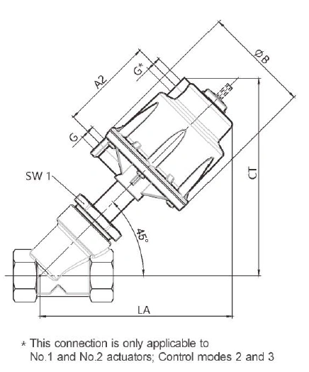
| Actuator size | ||||
| Pneumatic head | ΦB | M | A2 | G |
| 0 | 71 | M 16×1 | - | G 1/4 |
| 1+4 | 96 | M 16×1 | 85.5 | G 1/4 |
| 2 | 164 | M 22×1.5 | 123.0 | G 1/4 |
| Installation size/weight kg] | |||||||
| DN | Wrench opening degree SW1 |
Executor 0 | Executors 1 and 4 | Executors 2 | |||
| CT/LA | Weight | CT/LA | Weight | CT/LA | Weight | ||
| 15 | 36 | 153 | 0.9 | 164 | 1.4 | - | - |
| 20 | 41 | 163 | 1.1 | 174 | 1.6 | 241 | - |
| 25 | 46 | 163 | 1.3 | 174 | 1.8 | 241 | - |
| 32 | 55 | - | - | 182 | 2.4 | 249 | 4.6 |
| 40 | 60 | - | - | 187 | 2.7 | 254 | 5.5 |
| 50 | 75 | - | - | 195 | 3.4 | 262 | 6.4 |
| 65 | 75 | - | - | - | - | 275 | 8.5 |
| 80 | 75 | - | - | - | - | 292 | 9.6 |
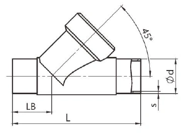
| Welding connection, connection codes 0,16,17,18,55,37,59,60 Valve body material 1.4435 (code 34) |
||||||||||||||||
| Connection code | ||||||||||||||||
| DN | Material code 34 | 0 | 16 | 17 | 18 | 55/37 | 59 | 60 | ||||||||
| L | LB | Φd | S | Φd | S | Φd | S | Φd | S | Φd | S | Φd | S | Φd | S | |
| 15 | 100 | 33 | 18 | 1.5 | 18 | 1.0 | 19 | 1.5 | 20 | 2.0 | 12.70 | 1.2 | 12.70 | 1.65 | 21.3 | 1.6 |
| 20 | 108 | 33 | 22 | 1.5 | 22 | 1.0 | 23 | 1.5 | 24 | 2.0 | 19.05 | 1.2 | 19.05 | 1.65 | 26.9 | 1.6 |
| 25 | 112 | 32 | 28 | 1.5 | 28 | 1.0 | 29 | 1.5 | 30 | 2.0 | 25.0 | 1.2 | 25.40 | 1.65 | 33.7 | 2.0 |
| 32 | 137 | 39 | - | - | 34 | 1.0 | 35 | 1.5 | 36 | 2.0 | - | - | - | - | 42.4 | 2.0 |
| 40 | 146 | 40 | 40 | 1.5 | 40 | 1.0 | 41 | 1.5 | 42 | 2.0 | 38.0 | 1.2 | 38.10 | 1.65 | 48.3 | 2.0 |
| 50 | 160 | 38 | 52 | 1.5 | 52 | 1.0 | 53 | 1.5 | 54 | 2.0 | 51.0 | 1.2 | 50.80 | 1.65 | 60.3 | 2.0 |
| 65 | 290 | 96 | - | - | - | 70 | 2.0 | - | - | 63.5 | 1.6 | 63.50 | 1.65 | 76.1 | 2.0 | |
| 80 | 310 | 95 | - | - | - | 85 | 2.0 | - | - | 76.1 | 1.6 | 76.20 | 1.65 | 88.9 | 2.3 | |
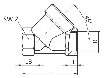
| Internal thread DIN, connection code 1 Valve body material 1.4408 (code 37) |
||||||
| DN | L | LB | R | t | SW2 | |
| 15 | 65 | 16.5 | G1/2 | 15.0 | 27 | HEXAGON |
| 20 | 75 | 17.5 | G3/4 | 16.3 | 32 | HEXAGON |
| 25 | 90 | 24.0 | G1 | 19.1 | 41 | HEXAGON |
| 32 | 110 | 33.0 | G11/4 | 21.4 | 50 | STAR ANISE |
| 40 | 120 | 30.0 | G11/2 | 21.1 | 55 | STAR ANISE |
| 50 | 150 | 40.0 | G 2 | 25.7 | 70 | STAR ANISE |
| 65 | 190 | 46.0 | G 21/2 | 30.2 | 85 | STAR ANISE |
| 80 | 220 | 50.0 | G3 | 33.3 | 100 | STAR ANISE |
| Materials refer to the list | ||||||
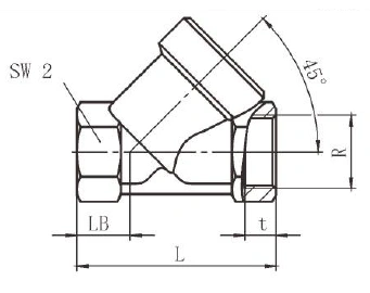
| BS21 Rc, Connection code 3C Valve body material 1.4408 (code 37) |
||||||
| DN | L | LB | SW2 | Connection code | ||
| 3C | ||||||
| R | t | |||||
| 15 | 65 | 16.5 | 27 | HEXAGON | Rc 1/2 | 15.0 |
| 20 | 75 | 17.5 | 32 | HEXAGON | Rc 3/4 | 16.3 |
| 25 | 90 | 24.0 | 41 | HEXAGON | Rc 1 | 19.1 |
| 32 | 110 | 33.0 | 50 | STAR ANISE | Rc 11/4 | 21.4 |
| 40 | 120 | 30.0 | 55 | STAR ANISE | Rc 11/2 | 21.4 |
| 50 | 150 | 40.0 | 70 | STAR ANISE | Rc 2 | 25.7 |
| 65 | 190 | 46.0 | 85 | STAR ANISE | Rc 21/2 | 30.2 |
| 80 | 220 | 50.0 | 100 | STAR ANISE | Rc 3 | 33.3 |
| Materials refer to the list | ||||||
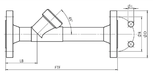
| Flange, connection code 8 Valve body material 1.4435 (code 34) |
||||||
| DN | FTF | LB | Connection code 8 | |||
| ΦD | ΦL | Φk | Number of bolts | |||
| 15 | 210 | 58 | 95 | 14 | 65 | 4 |
| 20 | 280 | 61 | 105 | 14 | 75 | 4 |
| 25 | 280 | 60 | 115 | 14 | 85 | 4 |
| 32 | 310 | 67 | 140 | 18 | 100 | 4 |
| 40 | 320 | 68 | 150 | 18 | 110 | 4 |
| 50 | 330 | 67 | 165 | 18 | 125 | 4 |
| 65 | 380 | 126 | 185 | 18 | 145 | 4 |
| 80 | 380 | 130 | 200 | 18 | 160 | 8 |
| Materials refer to the list | ||||||
| Take over | |||||||
| Connection code | 0 | 16 | 17 | 18 | 55/37 | 59 | 60 |
| Material Code | 34 | 34 | 34 | 34 | 34 | 34 | 34 |
| DN 15 | X | X | X | X | X | X | X |
| DN 20 | X | X | X | X | X | X | X |
| DN 25 | X | X | X | X | X | X | X |
| DN 32 | X | X | X | X | X | - | X |
| DN 40 | X | X | X | X | X | X | X |
| DN 50 | X | X | X | X | X | X | X |
| DN 65 | - | - | X | - | X | X | X |
| DN 80 | - | - | X | - | X | X | X |
| Threaded connection | Flange | ||
| Connection code | 1 | 3C | 8 |
| Material Code | 37 | 37 | 34 |
| Valve body structure | Direct valve body | ||
| DN 15 | X | X | X |
| DN 20 | X | X | X |
| DN 25 | X | X | X |
| DN 32 | X | X | X |
| DN 40 | X | X | X |
| DN 50 | X | X | X |
| DN 65 | X | X | X |
| DN 80 | X | X | X |
Lorem ipsum dolor sit amet, consectetur adipiscing elit. Aenean euismod bibendum laoreet. Proin gravida dolor sit amet lacus accumsan et viverra justo commodo. Proin sodales pulvinar sic tempor. Sociis natoque penatibus et magnis dis parturient montes, nascetur ridiculus mus. Nam fermentum, nulla luctus pharetra vulputate, felis tellus mollis orci, sed rhoncus pronin sapien nunc accuan eget.

Fields marked with * are required.