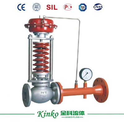
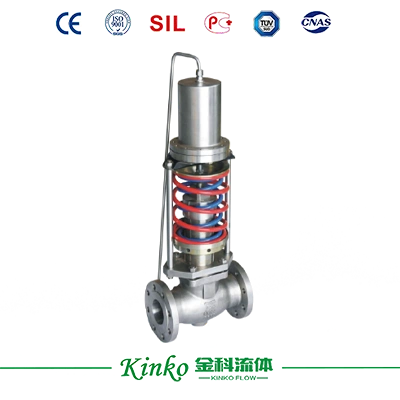
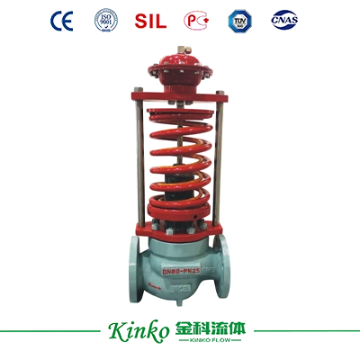
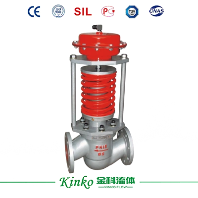
As long as the valve uses auxiliary energy cannot be called "self-operated", this concept must be clarified, otherwise it will cause misunderstandings for suppliers and manufacturers! There are four categories of self-operated valves: self-operated pressure regulating valves, self-operated temperature regulators Valves, self-operated flow control valves, and self-operated liquid level control valves. Among them, there are the most types of self-operated pressure control valves. There are the following types: 211 type pressure regulating valve, 212 type micro-pressure valve, 213 type differential pressure valve, 214-16 II type commander, and 216 type all-weather fire-resisting breathing valve.
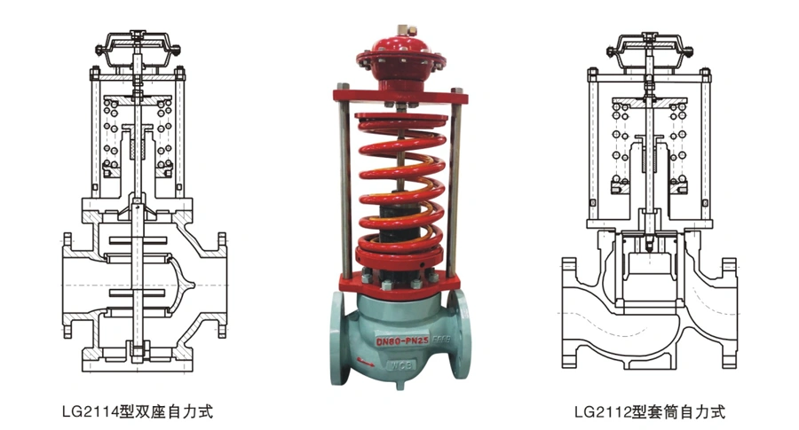
The 211 type self operated pressure regulating valve is an executive product that does not require any external energy and utilizes the energy of the regulated medium to automatically regulate. The biggest feature of this product is that it can be used in places without electricity or gas, while also saving energy. The pressure is not regularly adjustable within a certain range. The 211 type self-operated pressure regulating valve has three types of valve trim strokes according to the needs of various process occasions: the 2111 type (single-seat self-operated pressure regulating valve); 2112 type (sleeve self-operated pressure regulating valve); 2114 type (double-seat self-operated pressure regulating valve). Users can choose based on the conditions (pressure difference, temperature, medium status) and leakage requirements. The 211 type self-operated pressure regulating valve has three types of valve covers according to the needs of various process occasions: ordinary (general occasions), long nec (large pressure regulating range), and heat dissipation (temperature 350~550 ℃).
The 211 type self-operated pressure regulating valve has three types of actuators according to the needs of various process occasions: diaphragm (ordinary diaphragm and reinforced diaphragm), piston, and metal diaphragm (OCr18Ni9). The 211 type self operated pressure regulating valve adopts a fast opening flow characteristic, with sensitive action and high adjustment accuracy (error ≤ 10%); The valve occupies a small space (compared with the weight type pressure reducing valve) and is easy to adjust, so it is widely used in petroleum, chemical industry, power, metallurgy, food, textile, machinery manufacturing, civil buildings and other unprepared gas, liquid and steam pressure reduction and stabilization (for post valve regulation) or pressure relief and stabilization (for pre valve regulation).

Structure and Principle
The 211 type self-operated pressure regulating valve consists of a detection actuator, valve body, and front (rear) connecting pipe of the pressure pipe valve.
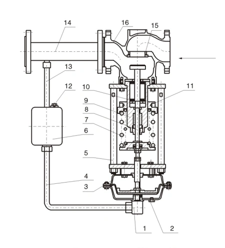
Figure 1a. The regulating valve used to control the pressure behind the valve, with a pressure-closed valve action mode.
The principle of its use is as follows:
The medium flows into the valve body in the direction of the arrow and is throttled by the valve seat and valve core before being output. Another path of the pressure pipe (adding condensate when the medium is steam) is introduced into the actuator and diaphragm, causing the valve core to move accordingly, achieving the purpose of reducing pressure and stabilizing pressure. If the pressure behind the valve increases, the force acting on the diaphragm increases, compressing the spring and driving the valve core to reduce the valve opening until the pressure behind the valve drops to the set value. Similarly, if the pressure behind the valve decreases, the force acting on the diaphragm decreases. Due to the reaction force of the spring, it drives the valve core and increases the opening of the valve until the pressure behind the valve rises to the set value.
Figure 1b: A regulating valve used to control the pressure in front of the valve. The valve operates in a pressure-open type, and its working principle is as follows: the medium flows into the valve body in an arrow pattern and is output after being throttled by the valve seat and core. The other path of the pressure pipe (adding a condenser when the medium is steam) is guided by the actuator to act on the diaphragm, causing the valve core to undergo corresponding displacement, achieving the purpose of pressure relief and stabilization. If the pressure in front of the valve increases, the force acting on the diaphragm increases, compressing the spring, driving the valve core, and increasing the opening of the valve until the pressure in front of the valve drops to the set value. Similarly, if the pressure in front of the valve decreases, the force acting on the diaphragm decreases. Due to the reaction force of the spring, it drives the valve core, causing the opening of the valve to decrease until the pressure in front of the valve rises to the set value. If the pressure in front of the valve is less than the set value, the valve remains closed.
 |
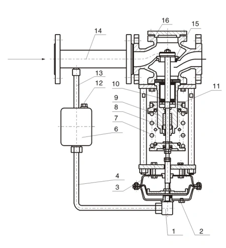 |
| Figure a: Type 2111-16B |
Figure b: Models 2111 and 16K |
|
Single-seat self-operated pressure-regulating valve
(downstream pressure control)
1. Drain plug 2. Vent plug 3. Actuator 4. Liquid inlet pipe
5. Gland screw 6. Condenser 7. Spring 8. Valve stem
9. Valve plug 10. Threaded pipe 11. Pressure adjustment disc
12. Liquid filling port screw 13. Steam inlet
14. Downstream connection pipe 15. Valve seat 16. Valve body
|
1. Drain plug 2. Vent plug 3. Actuator 4. Liquid inlet pipe
5. Gland screw 6. Condenser 7. Spring 8. Valve stem
9. Valve plug 10. Threaded tube 11. Pressure adjustment disc
12. Liquid filling port screw 13. Steam inlet
14. Outlet pipe 15. Valve seat 16. Valve body |