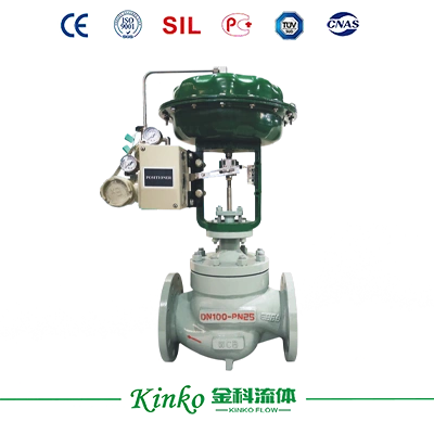
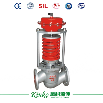
Basic structure of 111 type pneumatic thin film single seat regulating valve
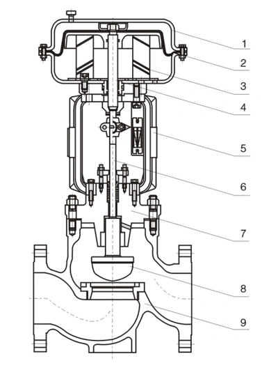 |
1. Diaphragm cover |
6. Valve stem |
| 2. Diaphragm |
7. Bonnet
(Standard type) |
| 3. Spring |
7. Bonnet
(Ambient temperature type) |
| 4. Push rod |
8. Valve plug |
| 5. Yoke |
9. Valve body |
Main technical parameters
Nominal Diameter
DN (mm) |
20 |
25 |
32 |
40 |
50 |
Valve seat diameter
dn(mm) |
10 |
12 |
15 |
20 |
10 |
12 |
15 |
20 |
25 |
32 |
32 |
40 |
32 |
40 |
50 |
Straight line
(KV) |
1.8 |
2.8 |
4.4 |
6.9 |
1.8 |
2.8 |
4.4 |
6.9 |
11 |
17.8 |
17.6 |
27.5 |
17.6 |
27.5 |
44 |
Rated flow coefficient
(KV) |
Straight line |
1.6 |
2.5 |
4.0 |
6.3 |
1.6 |
2.5 |
4.0 |
6.3 |
10 |
16 |
16 |
25 |
16 |
25 |
40 |
| Equal percentage |
| Rated stroke L |
16 |
25 |
Effective area Ae of membrane
Ae(cm²) |
280 |
400 |
Valve seat diameter
DN (mm) |
65 |
80 |
100 |
125 |
150 |
200 |
250 |
Valve seat diameter
dn(mm) |
65 |
65 |
80 |
65 |
80 |
100 |
125 |
125 |
150 |
150 |
200 |
250 |
Rated flow coefficient
(KV) |
Straight line |
69 |
69 |
110 |
69 |
110 |
176 |
275 |
275 |
440 |
440 |
690 |
1100 |
| Equal percentage |
63 |
63 |
100 |
63 |
100 |
160 |
250 |
250 |
400 |
400 |
630 |
900 |
| Rated stroke L |
40 |
60 |
100 |
Effective area Ae of membrane
Ae (cm²) |
600 |
1000 |
1600 |
Nominal pressure
PN |
Mpa |
1.6, 2.5, 4.0, 6.4(6.3)/2.0, 5.0, 11.0 |
| Bar |
16, 25, 40, 64(64)/20, 50, 110 |
| Lb |
ANSI:Class150, Class300, Class600 |
| Inherent flow characteristics |
Straight line, equal percentage |
Inherently adjustable ratio
(R) |
50:1 |
Spring (signal) range
Pr (kPa) |
20~100, 40~200, 80~240, (20~60, 60~100) |
Origin pressure
Ps(Mpa) |
0.14/0.25/0.3 |
| Permissible leakage amount |
Hard valve core: Class IV (10 x Kv); Soft valve core: Class VI, see GB/T4213-2008 |
Work temperature
(℃) |
Normal temperature type |
|
-20~200, -40~250, -60~250 |
| Heat dissipation type |
Code: S |
-40~350, -60~350 |
| High-temperature type |
Code: G |
350~550 (Select high-temperature materials) |
| Low temperature type |
Code: D |
-100~-60;-196~-100;-253~-196 |
| Adjusting the shut-off valve |
Code: Q |
-40~150 AD15(PTFE) |
1. Spring range: For the air-open type, 40-200KPa and 80-240KPa are preferred; 20-100KPa and 40-20OKPa are preferred for the air-closed type, and other spring ranges can be selected.
2. The classification of working temperature is based on comprehensive factors such as the pressure-temperature grade of the valve body material (GB/T12224-2015), operating conditions, and the sealing material of the valve. There are slight differences in classification among countries, and even each
The use of different materials by manufacturers can also result in different temperature divisions.
Connection dimensions and standards
The flange can be according to GB/T9124.1-2019 (default standard) or JB/T79-2015 or HG20592~HG20635-2009
Flange sealing surface type: PN16 is a raised-face flange; PN25 is a raised-face flange; PN40, PN64 (63) are concave-convex flanges, and the valve body is a concave flange
The distance between flange end faces shall be in accordance with GB/T12221-2005 (other standards must be specified)
Welding connection groove according to GB/T12224-2015
Pneumatic signal interface of actuator: Rc1/4, Rc3/8 (DN ≥ 250)
The distance between the valve body flange and the flange end face can be manufactured according to user-specified standards, such as ANSI, JIS, DIN, etc.
Valve cover type
| Part Name |
Material |
| Valve body, valve cover |
WCB(ZG230-450), WCC(ZG270-500), WC6(ZG15CrMo)
CF8(304), CF8M(316), CF3(304L), CF3M(316L) |
| Valve core and valve seat |
304(0Cr18Ni9), 316(0Cr17Ni12Mo2), 316L(00Cr17Ni14Mo2)
And overlay welding of Stellite alloy 17-4PH (precipitation-hardening stainless steel) |
| Filler |
PTFE (polytetrafluoroethylene), PTFE (reinforced polytetrafluoroethylene), Grafoil (flexible graphite) |
| Sealing gasket |
PTFE, stainless steel with graphite clip |
| Membrane cover |
A3 (Q235 painted or sprayed) 304 (used in special cases) |
| Corrugated diaphragm |
Nitrile rubber clip nylon |
| Spring |
6OSi2Mn 50CrVA |
| Valve stem |
304 316 316L 17-4PH |
Weight table of regulating valve
Unit: kg
| Nominal Diameter |
20 |
25 |
32 |
40 |
50 |
65 |
80 |
100 |
125 |
150 |
200 |
| Standard Type |
PN16 |
17 |
18 |
23 |
26 |
29 |
52 |
62 |
95 |
115 |
152 |
235 |
| PN40 |
18 |
19 |
25 |
27 |
32 |
56 |
68 |
115 |
140 |
165 |
295 |
| PN64 |
25 |
27 |
35 |
41 |
45 |
69 |
78 |
155 |
190 |
255 |
355 |
| Heat dissipation high-temperature type |
18 |
19 |
25 |
27 |
32 |
56 |
68 |
75 |
120 |
148 |
325 |
| Bellows-sealed type |
18 |
19 |
25 |
27 |
32 |
56 |
68 |
75 |
120 |
148 |
325 |
| Low temperature type |
25 |
27 |
30 |
33 |
39 |
59 |
68 |
85 |
150 |
210 |
335 |
Note: 1. Weight does not include attachment 2. For bellows-sealed type, high-temperature heat-dissipation type, and low-temperature type, take PN16 as an example
Allowable pressure difference (air open)
Unit: mm
| Effective area Ae of membrane (cm²) |
280 |
400 |
600 |
1000 |
| Signal range Pr (kPa) |
20-100 |
40-200 |
20-100 |
40-200 |
20-100 |
40-200 |
20-100 |
40-200 |
| Onigin pressure Ps (MPa) |
0.14 |
0.25 |
0.14 |
0.25 |
0.14 |
0.25 |
0.14 |
0.25 |
| Accessories required |
- |
P |
|
P |
- |
P |
- |
P |
Nominal diameter
DN(mm)
and
valve seat diameter
dn(mm) |
20 |
10 |
5.35 |
6.40 |
|
|
|
|
|
|
| 12 |
3.72 |
6.40 |
|
|
|
|
|
|
| 15 |
2.38 |
5.55 |
|
|
|
|
|
|
| 20 |
1.34 |
3.12 |
|
|
|
|
|
|
| 25 |
25 |
0.86 |
2.00 |
|
|
|
|
|
|
| 32 |
32 |
|
|
0.75 |
1.74 |
|
|
|
|
| 40 |
25 |
|
|
1.22 |
2.85 |
|
|
|
|
| 32 |
|
|
0.75 |
1.74 |
|
|
|
|
| 40 |
|
|
0.48 |
1.11 |
|
|
|
|
| 50 |
32 |
|
|
0.75 |
1.74 |
|
|
|
|
| 40 |
|
|
0.48 |
1.11 |
|
|
|
|
| 50 |
|
|
0.31 |
0.71 |
|
|
|
|
| 65 |
65 |
|
|
|
|
0.27 |
0.63 |
|
|
| 80 |
50 |
|
|
|
|
0.46 |
1.07 |
|
|
| 65 |
|
|
|
|
0.27 |
0.63 |
|
|
| 80 |
|
|
|
|
0.18 |
0.42 |
|
|
| 100 |
65 |
|
|
|
|
0.27 |
0.63 |
|
|
| 80 |
|
|
|
|
0.18 |
0.42 |
|
|
| 100 |
|
|
|
|
0.11 |
0.23 |
|
|
| 125 |
125 |
|
|
|
|
|
|
0.12 |
0.28 |
| 150 |
100 |
|
|
|
|
|
|
0.19 |
0.44 |
| 125 |
|
|
|
|
|
|
0.12 |
0.24 |
| 150 |
|
|
|
|
|
|
0.09 |
0.20 |
| 200 |
125 |
|
|
|
|
|
|
0.12 |
0.28 |
| 150 |
|
|
|
|
|
|
0.09 |
0.20 |
| 200 |
|
|
|
|
|
|
0.05 |
0.11 |
1. P: Valve positioner (air-opening type with or without a positioner does not affect the allowable pressure difference).
2. For the 111 single-seat corrugated pipe sealing regulating valve, the maximum allowable pressure difference is 1.0MPa. If the value in the table is less than 1. OMPa, it remains unchanged. If the value is greater than 1.0MPa, it is taken as 1.0MPa.
3. The allowable pressure difference only refers to the value configured according to the standard actuator, and an additional actuator can be configured according to specific operating conditions to meet the usage requirements.
4. Due to differences in the output force of actuators used by various domestic and foreign manufacturers, the allowable pressure difference data provided by each supplier for valves of the same caliber are different.
5. The allowable pressure difference of the 40-20OKPa spring used for the same valve is twice that of the 20-10KPa spring. From the above data, it can be seen that the air-open single-seat regulating valve should use 40-200KPa spring or 80-240KPa spring as much as possible.
6. The above data is based on the calculated value when the valve is closed and the pressure behind the valve P2=0, allowing for a larger pressure difference during adjustment.
Allowable pressure difference (air closed)
Unit: mm
| Effective area Ae of membrane (cm²) |
280 |
400 |
600 |
1000 |
| Signal range Pr(KPa) |
20-100 |
20-100 |
40-200 |
20-100 |
20-100 |
40-200 |
20-100 |
20-100 |
40-200 |
20-100 |
20-100 |
40-200 |
| Origin pressure Ps(MPa) |
0.14 |
0.14 |
0.25 |
0.14 |
0.14 |
0.25 |
0.14 |
0.14 |
0.25 |
0.14 |
0.14 |
0.25 |
| Accessories required |
|
P |
P |
- |
P |
P |
- |
P |
P |
- |
P |
P |
Nominal diameter
DN (mm)
and
valve seat diameter
dn (mm) |
20 |
10 |
5.35 |
6.40 |
6.40 |
|
|
|
|
|
|
|
|
|
| 12 |
3.72 |
6.40 |
6.40 |
|
|
|
|
|
|
|
|
|
| 15 |
2.33 |
5.55 |
6.40 |
|
|
|
|
|
|
|
|
|
| 20 |
1.34 |
3.12 |
4.01 |
|
|
|
|
|
|
|
|
|
| 25 |
25 |
0.86 |
2.00 |
2.57 |
|
|
|
|
|
|
|
|
|
| 32 |
32 |
|
|
|
0.75 |
1.74 |
2.24 |
|
|
|
|
|
|
| 40 |
25 |
|
|
|
1.22 |
2.85 |
3.67 |
|
|
|
|
|
|
| 32 |
|
|
|
0.75 |
1.74 |
2.24 |
|
|
|
|
|
|
| 40 |
|
|
|
0.48 |
1.11 |
1.48 |
|
|
|
|
|
|
| 50 |
32 |
|
|
|
0.75 |
1.74 |
2.24 |
|
|
|
|
|
|
| 40 |
|
|
|
0.48 |
1.11 |
1.48 |
|
|
|
|
|
|
| 50 |
|
|
|
0.31 |
0.71 |
0.91 |
|
|
|
|
|
|
| 65 |
65 |
|
|
|
|
|
|
0.27 |
0.63 |
0.81 |
|
|
|
| 80 |
50 |
|
|
|
|
|
|
0.46 |
1.07 |
1.38 |
|
|
|
| 65 |
|
|
|
|
|
|
0.27 |
0.63 |
0.81 |
|
|
|
| 80 |
|
|
|
|
|
|
0.18 |
0.42 |
0.52 |
|
|
|
| 100 |
65 |
|
|
|
|
|
|
0.27 |
0.63 |
0.81 |
|
|
|
| 80 |
|
|
|
|
|
|
0.18 |
0.42 |
0.52 |
|
|
|
| 100 |
|
|
|
|
|
|
0.11 |
0.26 |
0.34 |
|
|
|
| 125 |
125 |
|
|
|
|
|
|
|
|
|
0.12 |
0.29 |
0.37 |
| 150 |
100 |
|
|
|
|
|
|
|
|
|
0.19 |
0.44 |
0.57 |
| 125 |
|
|
|
|
|
|
|
|
|
0.12 |
0.29 |
0.37 |
| 150 |
|
|
|
|
|
|
|
|
|
0.09 |
0.20 |
0.25 |
| 200 |
125 |
|
|
|
|
|
|
|
|
|
0.12 |
0.29 |
0.37 |
| 150 |
|
|
|
|
|
|
|
|
|
0.09 |
0.20 |
0.25 |
| 200 |
|
|
|
|
|
|
|
|
|
0.05 |
0.11 |
0.14 |
1. P: Valve Positioner
2. For the 111 type single-seat corrugated pipe sealing regulating valve, the maximum allowable pressure difference is 1.0MPa. If the value in the table is less than 1.0MPa, it remains unchanged. If the value is greater than 1.0MPa, it is taken as 1.0MPa.
3. The allowable pressure difference only refers to the value configured according to the standard actuator, and an additional actuator can be configured according to specific operating conditions to meet the usage requirements.
4. When the air source pressure is the same, the allowable pressure difference between 80-240Kpa spring and 40-200Kpa spring is the same (without a locator). From the above data, it can be seen that the air-closed single-seat regulating valve should be used as much as possible 40-200Kpa spring range or 20-100Kpa spring range.
5. The above data is based on the calculated value when the valve is closed and the pressure behind the valve P2=0, allowing for a larger pressure difference during adjustment.
Overall dimensions
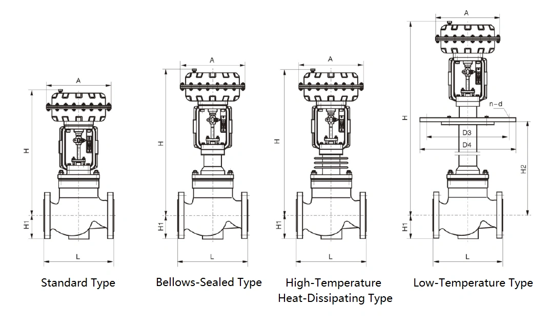
Outline dimension table for standard type, bellows sealed type, and high-temperature heat dissipation type
Unit: mm
| Nominal Diameter |
20 |
25 |
32 |
40 |
50 |
65 |
80 |
100 |
125 |
150 |
200 |
250 |
| ΦA |
282 |
308 |
395 |
498 |
620 |
| L |
PN16,20,25,40
ANSI150lb |
150 |
160 |
180 |
200 |
230 |
290 |
310 |
350 |
400 |
480 |
600 |
730 |
PN64,100(110)
ANSI300lb, 600Lb |
230 |
230 |
260 |
260 |
300 |
340 |
380 |
430 |
500 |
550 |
650 |
775 |
| H1 |
PN16 |
52.5 |
57.5 |
70 |
75 |
82.5 |
92.5 |
100 |
110 |
125 |
142.5 |
170 |
202.5 |
| PN25 |
52.5 |
57.5 |
70 |
75 |
82.5 |
92.5 |
100 |
115 |
135 |
150 |
180 |
212.5 |
| PN40 |
52.5 |
57.5 |
70 |
75 |
82.5 |
92.5 |
100 |
117.5 |
135 |
150 |
187.5 |
225 |
| PN64(63) |
65 |
70 |
78 |
85 |
90 |
102.5 |
107.5 |
125 |
147.5 |
172.5 |
202.5 |
235 |
| ANSI 150lb(PN20) |
50 |
55 |
60 |
85 |
75 |
80 |
95 |
115 |
127.5 |
140 |
172.5 |
202.5 |
| ANSI 300Lb(PN50) |
60 |
62.5 |
67.5 |
77.5 |
82.5 |
95 |
105 |
127.5 |
140 |
160 |
190 |
222.5 |
| H |
Standard Type |
PN16/25/40 |
400 |
400 |
440 |
450 |
460 |
570 |
570 |
570 |
670 |
700 |
740 |
970 |
| ANSI 150lb(PN20) |
400 |
400 |
440 |
450 |
460 |
570 |
570 |
570 |
670 |
700 |
740 |
970 |
| PN64,300lb(PN50) |
400 |
400 |
450 |
450 |
460 |
570 |
570 |
570 |
720 |
750 |
750 |
980 |
| Heat dissipation, high-temperature corrugated pipe sealing type |
480 |
480 |
530 |
530 |
530 |
640 |
640 |
640 |
800 |
810 |
840 |
1050 |
1. The height of the valve with a top-mounted handwheel mechanism should be increased by 152 (DN20-50), 182 (DN65-100), 253 (DN125-200), and 352 (DN250)
Overall dimensions
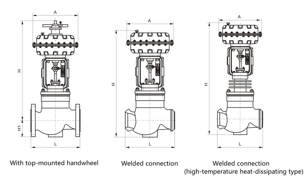
Low-temperature type external dimension table (American standard)
Unit: mm
| Nominal Diameter |
20 |
25 |
32 |
40 |
50 |
65 |
80 |
100 |
125 |
150 |
200 |
| ΦA |
282 |
308 |
395 |
498 |
| L |
PN16,20
(150lb)25,40 |
150 |
160 |
180 |
200 |
230 |
290 |
310 |
350 |
400 |
480 |
600 |
PN50(300Lb)
64(63) |
230 |
230 |
260 |
260 |
300 |
340 |
380 |
430 |
500 |
550 |
650 |
| H1 |
-60~-100℃ |
500 |
500 |
500 |
500 |
500 |
600 |
600 |
600 |
700 |
700 |
700 |
| -100~-200℃ |
700 |
700 |
700 |
700 |
700 |
800 |
800 |
800 |
900 |
900 |
900 |
| -200~-250℃ |
900 |
900 |
900 |
900 |
900 |
1000 |
1000 |
1000 |
1100 |
1100 |
1100 |
1. The height of the valve with top mounted handwheel mechanism should be increased by 152 (DN20-50), 182 (DN65-100), and 253 (DN125-200)
2. The size H2 (insulation length) is recommended based on the design size of the general air separation industry. The design institute and user unit can specify it according to their needs. If not specified, our company will produce according to the above dimensions.
Low temperature type external dimension table (national standard)
Unit: mm
| Nominal Diameter |
20 |
25 |
32 |
40 |
50 |
65 |
80 |
100 |
125 |
150 |
200 |
| H |
-60~
-100℃ |
Pn16, 20, 25, 40 |
810 |
810 |
832 |
832 |
832 |
1026 |
1026 |
1026 |
1200 |
1198 |
1198 |
| Pn50, 64 |
810 |
810 |
832 |
832 |
832 |
1026 |
1026 |
1026 |
1200 |
1198 |
1198 |
-100~
-200℃ |
Pn16, 20, 25, 40 |
1010 |
1010 |
1032 |
1032 |
1032 |
1226 |
1226 |
1226 |
1400 |
1398 |
1398 |
| Pn50, 64 |
1010 |
1010 |
1032 |
1032 |
1032 |
1226 |
1226 |
1226 |
1400 |
1398 |
1398 |
-200~
-250℃ |
PN16, 20, 25, 40 |
1210 |
1210 |
1232 |
1232 |
1232 |
1426 |
1426 |
1426 |
1600 |
1598 |
1598 |
| PN50, 64 |
1210 |
1210 |
1232 |
1232 |
1232 |
1426 |
1426 |
1426 |
1600 |
1598 |
1598 |
| ΦD3 |
260 |
260 |
285 |
305 |
340 |
370 |
405 |
460 |
525 |
590 |
700 |
| ΦD4 |
290 |
290 |
315 |
335 |
370 |
400 |
435 |
490 |
555 |
630 |
740 |
| Bolt holes: n (quantity), d (diameter) |
8-14 |
8-14 |
8-14 |
8-16 |
8-16 |
10-16 |
10-16 |
12-18 |
14-18 |
16-18 |
18-18 |
1. The height of the valve with a top-mounted handwheel mechanism should be increased by 152 (DN20-50), 182 (DN65-100), and 253 (DN125-200)
2. The size H2 (insulation length) is recommended based on the design size of the general air separation industry. The design institute and user unit can specify it according to their needs. If not specified, our company will produce it according to the above dimensions.