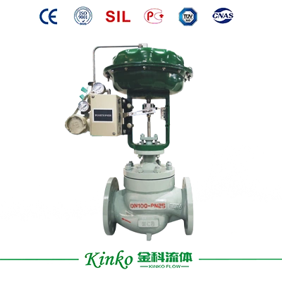
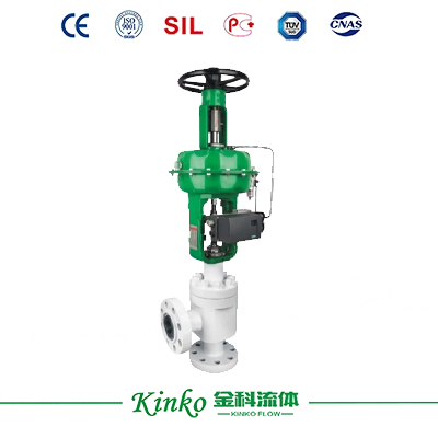
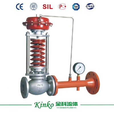
For downstream pressure-regulating valves (self-operated), if the pressure differential ratio across the valve exceeds 10:1, it is recommended to use a multi-stage pressure-reducing valve or two self-operated valves in series (except when the upstream pressure is below 0.8 MPa, such as with pilot-operated types).
Special handling is required if the nominal pressure exceeds 6.4 MPa.
1 kgf/cm² = 100 kPa.
Installation Considerations:
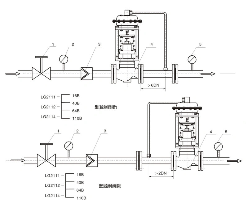
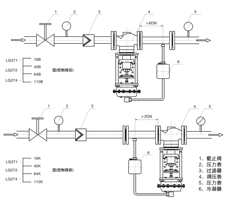
(1) The condenser must be positioned higher than the pressure-regulating valve's actuator but lower than the upstream and downstream connecting pipes. Fill the condenser with cold water before initial use and refill it approximately every three months thereafter.
(2) Select appropriate locations for pressure sensing points: the upstream sensing point should be at a distance greater than twice the pipe diameter from the valve, and the downstream sensing point should be at a distance greater than six times the pipe diameter.
(3) To facilitate on-site maintenance and operation, ensure adequate clearance around the regulating valve; install shut-off valves and a manual bypass valve upstream and downstream of the valve.
(4) If the pressure-regulating valve has a large nominal diameter (DN ≥ 100), a fixed support bracket must be installed.
(5) If the medium is confirmed to be very clean, "Item 3" need not be installed.
(6) The self-operated valve may have a smaller nominal diameter than the pipeline, but the filter and shut-off valves must not.
Model preparation instructions
2111--16 (25, 40, 64, 110) B 3001P-16K
2: Self-operated product series
1: Diaphragm actuator; 1: Direct-acting type; 1: Single-seat structure; 2: Cage-guided structure; 4: Double-seat structure; 16: PN 1.6 MPa, 40: 4.0 MPa
B: Controls downstream pressure (valve closes as pressure rises); K: Controls upstream pressure (valve opens as pressure rises)
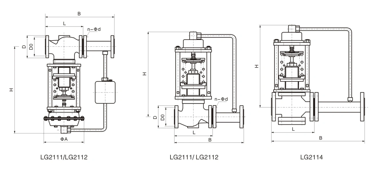
Connection dimensions and standards
Flanges comply with GB/T 9124.1-2019 (default standard); JB/T 79-2015 or HG 20592–HG 20635-2009 are also available upon request.
Flange sealing face types: Raised Face (RF) for PN16 and PN25; Tongue and Groove (T&G) for PN40 and PN64 (63), with the valve body featuring the Groove face.
Face-to-face dimensions comply with GB/T 12221-2005 (other standards must be specified).
Welding end bevels comply with GB/T 12224-2015.
Actuator pneumatic signal connections: Rc1/4, Rc3/8 (for DN ≥ 250).
Valve body flanges and face-to-face dimensions can be manufactured according to user-specified standards, such as ANSI, JIS, DIN, etc.
Pressure adjustment method
The self-operated pressure regulating valve is adjusted to the specified setpoint before leaving the factory; however, if the user wishes to change the setpoint, or if the actual indicated value deviates from the setpoint for any reason, the setting can be adjusted by turning the adjustment dial (7) with an adjustment rod: turning it clockwise decreases the pressure, while turning it counter-clockwise increases the pressure.