
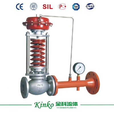
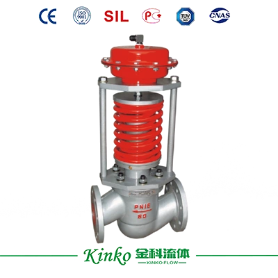
The 214 type self-operated pressure-regulating valve with a controller (referred to as the pressure valve) does not require external energy and uses the energy of the regulated medium as the power source.
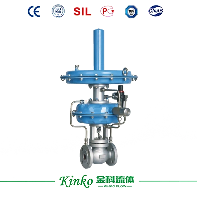
The 214 type self-operated pressure-regulating valve with a controller (referred to as the pressure valve) does not require external energy and uses the energy of the regulated medium as the power source.
The controller of the pressure valve is introduced to control the position of the valve core, change the flow rate of the medium flowing through the valve, and keep the rear pressure (B type) or front pressure (K) of the valve constant. The 214 type is mainly used for high front pressure (0.2-0.8MPa) and low rear pressure (0.5-100KPa), For example, in the case of 5mmH2O (water column), the 214 model is only used on the nitrogen relief device and is used in conjunction with the nitrogen supply device. Please use ZZVP valve instead when used alone.
1. Atmospheric pressure reduction
If the front of the valve is 0.2-0.8MPa (above 0.8MPa, a pressure-reducing valve should be added in front of the valve), and the back of the valve is 0.5-100 kPa.
2. Nitrogen sealing device
On nitrogen supply and discharge devices
Feature
1. The pressure setting is achieved on the controller, making it convenient, convenient, labor-saving, and time-saving, and it can be continuously set during operation.
2. The control accuracy is about twice that of the 211 type self-operated type, making it suitable for use in situations with high control accuracy.
3. For the same valve, the adjustment range is wider than the 211 self-operated type.
4. The reaction is particularly sensitive, and even extremely small pressures (such as a pressure of 50mm water column) or small pressure changes can be infected.
5. The pressure reduction ratio is particularly large, such as 0.8MPa in front of the valve and 50mmH2O behind the valve, with a pressure difference ratio of 1600.

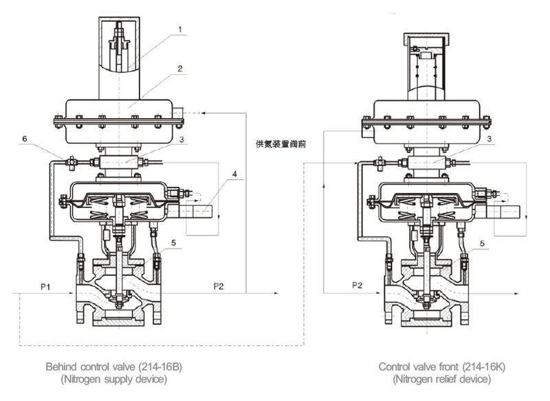
1. Pressure-setting spring 2. Command actuator 3. Command valve 4. Needle valve 5. Main valve 6. Air filter pressure reducer
The 214-16B valve can be replaced by one 2111 self-operated valve and one 212 micro pressure valve.
The 214-16K type valve can be replaced by one 212 type micro pressure valve.
Connection dimensions and standards
Flange standard: GB/T9124.1-2019.
Flange sealing surface type: convex surface.
Signal interface: internal thread M16 × 1.5.
The distance between the valve body flange and the flange end face can be manufactured according to user specified standards, such as ANSI, JIS, JPI, etc.
Model preparation instructions
2: Self-operated product series
1: Thin film actuator
4: Command operation type
Ordering Instructions
Please provide the following information when placing an order:
Name and model of pressure regulating valve
Nominal diameter (mm)
Nominal pressure (MPa)
Rated flow coefficient (Kv)
Inherent flow characteristics
Media Name
Working pressure and range
Other special requirements for valve body, trim, and packing materials
| Part Name | Material |
| Valve body | ZG230-450, ZGOCr18Ni9, ZGOCr18Ni12Mo2 |
| Spool | 1Cr18Ni9, OCr18Ni12Mo2 (Stellite) PTFE |
| Valve seat | 1Cr018Ni9, OCr18Ni12Mo2 (Stellite) |
| Valve stem | 1Cr18Ni9, OCr18Ni12Mo2 |
| Rubber diaphragm | Nitrile rubber clip adds strong polyester fabric |
| Membrane cover | Q235, PTFE-coated Q235 |
| O-ring | Oil-resistant rubber, polytetrafluoroethylene |
| Nominal diameter DN (mm) | 20 | 25 | 32 | 40 | 50 | 65 | 80 | 100 | 125 | 150 | ||
| Valve seat diameter D (mm) | 6 | 15 | 20 | 25 | 32 | 40 | 50 | 65 | 80 | 100 | 125 | 150 |
| Rated flow coefficient Kv | 0.32 | 4 | 5 | 8 | 12.5 | 20 | 32 | 50 | 80 | 125 | 160 | 320 |
| Pressure regulation range KPa | 0.5-100 Select within the scope | |||||||||||
| Nominal pressure PN (MPa) | 1.0 1.6 | |||||||||||
| Temperature of the adjusted medium (℃) | -40~80 | |||||||||||
| Flow characteristics | Quick open | |||||||||||
| Adjustment error (%) | ≤5 | |||||||||||
| Allowable pressure drop (MPa) | 1.6 | 1.6 | 1.1 | 0.4 | 0.6 | |||||||
| Effective area of actuator film (cm²) | 200 | 280 | 400 | |||||||||
| Permissible leakage | Hard valve core: Ⅳ (10⁻⁴ x Kv) Soft valve core: VI (GB/T4213-2008) | |||||||||||
1. Replacing the 212 type micro pressure valve
The 212 type micro pressure valve generally requires a medium pressure of ≤ 0.1MPa in front of the valve, while the 214B type self-operated pressure-regulating valve with a command is not subject to this restriction.
2. For nitrogen sealing device
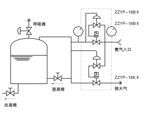
The upper end of the finished oil in the nitrogen sealing device is covered with nitrogen gas, and its pressure is generally around 100mmH2, which is controlled by the nitrogen sealing protection device. When the outlet valve is opened to drain oil, the liquid level in the outlet tank decreases. At this time, the opening of the 214B nitrogen supply regulating valve increases, and nitrogen is added to the outlet tank to increase the pressure to the set value. When the oil inlet valve is opened, the liquid level increases, the volume of the gas phase decreases, and the nitrogen pressure increases. At this time, the 214B nitrogen supply regulating valve is closed, while the 214B leakage regulating valve is opened under the action of a pressure controller, and nitrogen is discharged to reduce the pressure to the set value. To ensure the safety of the storage tank, a breathing valve should be installed on the top of the tank. Nitrogen supply pressure adjustment: When selecting the 214B pressure regulating valve with a set value of 1KPa (100mm. W. C), adjust the pre-compression (stretching) amount of the main spring 2 to achieve this; Nitrogen relief pressure adjustment: In the pressure controller part of the 214K relief valve, the main spring pre-compression shrinkage is adjusted to achieve. Generally, to avoid frequent opening and closing of the nitrogen sealing device, the nitrogen relief setting value should be far away from the nitrogen supply pressure setting value, such as 2KPa (200mm. W. C). Adjustment of the setting value of the breathing valve: After adjusting the above two settings, in order to avoid frequent opening and closing of the breathing valve, the setting value of the breathing valve should be greater than the pressure relief setting value. The two settings should not be too close together. The breathing valve model is: 216 type. The pressure setting value for the 214B type is Pc, and the pressure setting value for the 214K type is P1. The values of Pc and P1 should not be too close together to prevent the valve from working too frequently. The setting value for the discharge pressure P2 of the breathing valve should be greater than P1, and the values of P2 and F1 should not be too close together. The relationship between the three values is Pc
| DN | L | S | H1 | H | 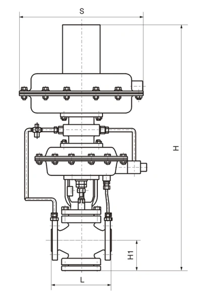 |
| 20 | 150 | 308 | 390 | 715 | |
| 25 | 160 | 308 | 390 | 715 | |
| 32 | 180 | 308 | 390 | 735 | |
| 40 | 200 | 394 | 435 | 755 | |
| 50 | 230 | 394 | 435 | 755 | |
| 65 | 290 | 394 | 435 | 795 | |
| 80 | 310 | 394 | 435 | 795 | |
| 100 | 350 | 394 | 435 | 825 | |
| 150 | 480 | 498 | 565 | 1105 |
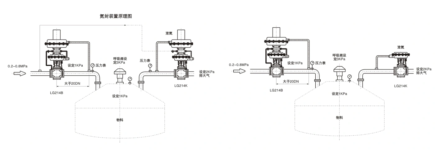
The above example takes the storage tank 1KPa as an example
1. The pressure tapping position of the 214B valve should be close to the storage tank (or buffer tank).
2. The pressure gauge should be located not far from the pressure measuring point to avoid unnecessary disputes.
3. The pipeline behind the 214B valve should not be too small (generally larger than the pipeline before the valve).

Lorem ipsum dolor sit amet, consectetur adipiscing elit. Aenean euismod bibendum laoreet. Proin gravida dolor sit amet lacus accumsan et viverra justo commodo. Proin sodales pulvinar sic tempor. Sociis natoque penatibus et magnis dis parturient montes, nascetur ridiculus mus. Nam fermentum, nulla luctus pharetra vulputate, felis tellus mollis orci, sed rhoncus pronin sapien nunc accuan eget.


Fields marked with * are required.