
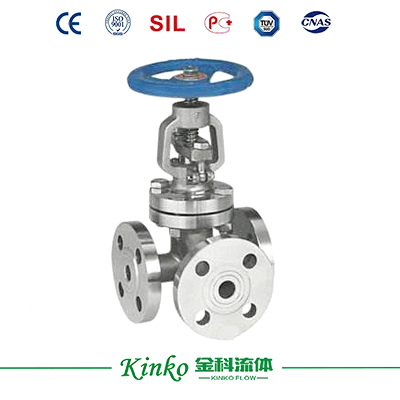
Model: J641H(F)
Size: DN50~800mm
Working Pressure: 0.6, 1.0, 1.6, 2.5, 4.0MPa; 150Lb, 300Lb
Design Standard: GB Standard, ANSI
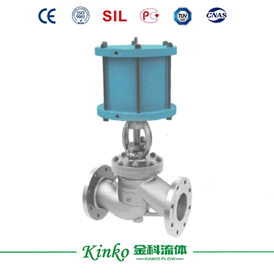
Model: J641H(F)
Size: DN50~800mm
Working Pressure: 0.6, 1.0, 1.6, 2.5, 4.0MPa; 150Lb, 300Lb
Design Standard: GB Standard, ANSI


Body Material: Carbon Steel (WCB), Stainless Steel (CF8, CF8M, CF3, CF3M)
Seat Material: Metal Sealed (H, Y), PTFE (F)
Mode of Action: Double-acting, Single-acting (Spring Return)
Mode of Control: ON/OFF Type, Adjusting Type
Annex Choice: Solenoid Valve, POSITIONER, Limit Switch, F.R.L.Manual Gear

| Design Basis | GB Standard | |
| Design Standard | GB/12234 | |
| Face-to-face dimension | Flange connecting | GB/12221 |
| Connecting Flange Size | GB/9113, JB/T79 | |
| Test &inspection | GB/T 13927, JB/T9092 | |
Note: The structural length and connecting flange size of the gate valve series can be designed and manufactured as per users’requirements.
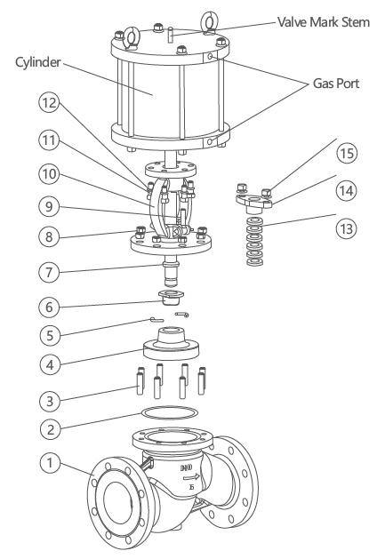 |
No. | Name of parts | Material | ||
| C | P | R | |||
| 1 | Body | WCB | ZG1Cr18Ni9Ti | ZG1Cr18Ni12Mo2Ti | |
| 2 | Gasket | Graphite+Stainless Steel | PTFE | PTFE | |
| 3 | Screw | 35 | 304 | 304 | |
| 4 | Disc | WCB body with 304 stainless steel or Stellite overlay; PTFE seat/seal. |
ZG1Cr18Ni9Ti PTFE |
ZG1Cr18Ni12Mo2Ti PTFE |
|
| 5 | Split ring | 1Cr18Ni9Ti | 1Cr18Ni9Ti | 1Cr18Ni12Mo2Ti | |
| 6 | Disc cover | 1Cr18Ni9Ti | 1Cr18Ni9Ti | 1Cr18Ni12Mo2Ti | |
| 7 | Sem | 2Cr13 | 1Cr18Ni9Ti | 1Cr18Ni12Mo2Ti | |
| 8 | Scre Cap | 35 | 304 | 304 | |
| 9 | Lifting Ring Screw | 35 | 304 | 304 | |
| 10 | Cover | WCB | ZG1Cr18Ni9Ti | ZG1Cr18Ni12Mo2Ti | |
| 11 | Screw | 35 | 304 | 304 | |
| 12 | Gasket | 35 | 1Cr18Ni9Ti | 1Cr18Ni12Mo2Ti | |
| 13 | Packing | Graphite | PTFE | PTFE | |
| 14 | Packing Plate | WCB | ZG1Cr18Ni9Ti | ZG1Cr18Ni12Mo2Ti | |
| 15 | Scre Cap | 35 | 304 | 304 | |
Note: The main spare parts and sealed seat material of the gate valve series can be designed as options as per users' special requirements.
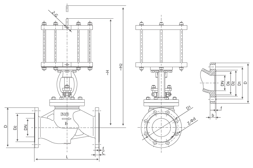
| Nominal diameter DN | Outline Dimension | Connecting Flange Size | Air Source Interface | |||||||
| L | ~H | D | D1 | D2 | C | f | N | Φd | ||
| 15 | 130 | 291 | 95 | 65 | 46 | 14 | 2 | 4 | 14 | 1/4" |
| 20 | 150 | 300 | 105 | 75 | 56 | 16 | 2 | 4 | 14 | |
| 25 | 160 | 353 | 115 | 85 | 65 | 16 | 2 | 4 | 14 | |
| 32 | 180 | 390 | 140 | 100 | 76 | 18 | 2 | 4 | 18 | |
| 40 | 200 | 518 | 150 | 110 | 84 | 18 | 3 | 4 | 18 | |
| 50 | 230 | 555 | 165 | 125 | 99 | 20 | 3 | 4 | 18 | |
| 65 | 290 | 630 | 185 | 145 | 118 | 20 | 3 | 4 | 18 | |
| 80 | 310 | 683 | 200 | 160 | 132 | 20 | 3 | 8 | 18 | |
| 100 | 350 | 745 | 220 | 180 | 156 | 22 | 3 | 8 | 18 | 3/8" |
| 125 | 400 | 855 | 250 | 210 | 184 | 22 | 3 | 8 | 18 | |
| 150 | 480 | 870 | 285 | 240 | 211 | 24 | 3 | 8 | 22 | |
| 200 | 600 | 954 | 340 | 295 | 266 | 24 | 3 | 12 | 22 | |
| 250 | 730 | 1065 | 405 | 355 | 319 | 26 | 3 | 12 | 26 | |
| 300 | 850 | 1185 | 460 | 410 | 370 | 28 | 4 | 12 | 26 | |
| Nominal diameter DN | Outline Dimension | Connecting Flange Size | Air Source Interface | |||||||
| L | ~H | D | D1 | D2 | C | f | N | Φd | ||
| 15 | 130 | 291 | 95 | 65 | 46 | 14 | 2 | 4 | 14 | 1/4" |
| 20 | 150 | 300 | 105 | 75 | 56 | 16 | 2 | 4 | 14 | |
| 25 | 160 | 353 | 115 | 85 | 65 | 16 | 2 | 4 | 14 | |
| 32 | 180 | 390 | 140 | 100 | 76 | 18 | 2 | 4 | 18 | |
| 40 | 200 | 518 | 150 | 110 | 84 | 18 | 3 | 4 | 18 | |
| 50 | 230 | 555 | 165 | 125 | 99 | 20 | 3 | 4 | 18 | |
| 65 | 290 | 630 | 185 | 145 | 118 | 22 | 3 | 8 | 18 | |
| 80 | 310 | 683 | 200 | 160 | 132 | 24 | 3 | 8 | 18 | |
| 100 | 350 | 745 | 235 | 190 | 156 | 24 | 3 | 8 | 22 | 3/8" |
| 125 | 400 | 855 | 270 | 220 | 184 | 26 | 3 | 8 | 26 | |
| 150 | 480 | 870 | 300 | 250 | 211 | 28 | 3 | 8 | 26 | |
| 200 | 600 | 954 | 360 | 310 | 274 | 30 | 3 | 12 | 26 | |
| 250 | 730 | 1065 | 425 | 370 | 330 | 32 | 3 | 12 | 30 | |
| 300 | 850 | 1185 | 485 | 430 | 389 | 34 | 4 | 16 | 30 | |
| Nominal diameter DN | Outline Dimension | Connecting Flange Size | Air Source Interface | |||||||||
| L | ~H | D | D1 | D2 | C | f | N | Φd | D3 | X | ||
| 15 | 130 | 305 | 95 | 65 | 46 | 14 | 2 | 4 | 14 | 40 | 4 | 1/4" |
| 20 | 150 | 315 | 105 | 75 | 56 | 16 | 2 | 4 | 14 | 51 | 4 | |
| 25 | 160 | 373 | 115 | 85 | 65 | 16 | 2 | 4 | 14 | 58 | 4 | |
| 32 | 180 | 416 | 140 | 100 | 76 | 18 | 2 | 4 | 18 | 66 | 4 | |
| 40 | 200 | 530 | 150 | 110 | 84 | 18 | 3 | 4 | 18 | 76 | 4 | |
| 50 | 230 | 575 | 165 | 125 | 99 | 20 | 3 | 4 | 18 | 88 | 4 | |
| 65 | 290 | 656 | 185 | 145 | 118 | 22 | 3 | 8 | 18 | 110 | 4 | |
| 80 | 310 | 713 | 200 | 160 | 132 | 24 | 3 | 8 | 18 | 121 | 4 | |
| 100 | 350 | 775 | 235 | 190 | 156 | 24 | 3 | 8 | 22 | 150 | 4.5 | 3/8" |
| 125 | 400 | 892 | 270 | 220 | 184 | 26 | 3 | 8 | 26 | 176 | 4.5 | |
| 150 | 480 | 940 | 300 | 250 | 211 | 28 | 3 | 8 | 26 | 204 | 4.5 | |
| 200 | 600 | 1054 | 375 | 320 | 284 | 34 | 3 | 12 | 30 | 260 | 4.5 | |
| 250 | 730 | 1115 | 450 | 385 | 345 | 38 | 3 | 12 | 33 | 313 | 4.5 | |
| 300 | 850 | 1235 | 515 | 450 | 409 | 42 | 4 | 16 | 33 | 364 | 4.5 | |
Note: The relative sizes are subject to change responding to different valve torques, mediums, and actuator models.

Lorem ipsum dolor sit amet, consectetur adipiscing elit. Aenean euismod bibendum laoreet. Proin gravida dolor sit amet lacus accumsan et viverra justo commodo. Proin sodales pulvinar sic tempor. Sociis natoque penatibus et magnis dis parturient montes, nascetur ridiculus mus. Nam fermentum, nulla luctus pharetra vulputate, felis tellus mollis orci, sed rhoncus pronin sapien nunc accuan eget.


Fields marked with * are required.