Technical Table
| Design Basis |
GB Standard |
ANSI Standard |
| Design Standard |
JB/T8691-1998 |
ANSI B16.34 |
| Connecting Standard |
GB/9113, JB/T79 |
ANSI B16.5 |
| Test &inspection |
JB/T9092 |
API 598 |
Note: The structural length and connecting flange size of the gate valve series can be designed and manufactured as per users’requirements.
Form of Main Parts Materials
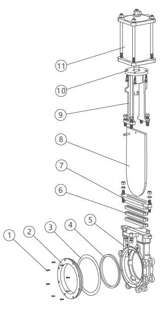 |
No. |
Name of parts |
Material |
| C |
P |
R |
| 1 |
Inner Hexagon Screw |
1Cr18Ni9Ti |
1Cr18Ni9Ti |
1Cr18Ni12Mo2Ti |
| 2 |
Cover |
WCB |
1Cr18Ni9Ti |
ZG1Cr18Ni12Mo2Ti |
| 3 |
Gasket |
PTFE |
PTFE |
PTFE |
| 4 |
Seat |
1Cr18Ni9Ti or PTFE, Rubber |
1Cr18Ni12Mo2T or PTFE, Rubber |
| 5 |
Body |
WCB |
ZG1Cr18Ni9Ti |
ZG1Cr18Ni12Mo2Ti |
| 6 |
Packing Material |
PTFE, PTFE Nirtile, Rubber or PTFE |
PTFE, PTFE Nirtile, Rubber or PTFE |
PTFE, PTFE Nirtile, Rubber or PTFE |
| 7 |
Gland |
WCB |
ZG1Cr¹8Ni9Ti |
ZG1Cr18Ni12Mo2Ti |
| 8 |
Shut-off Device |
1Cr18Ni9Ti |
1Cr18Ni9Ti |
1Cr18Ni12Mo2Ti |
| 9 |
Yoke |
WCB |
ZG1Cr18Ni9Ti |
ZG1Cr18Ni9Ti |
| 10 |
Push-and-pull Rod |
45# Steel Chrome Plating |
45# Steel Chrome Plating |
45# Steel Chrome Plating |
| 11 |
Pneumatic-Actuator |
ZTQD Series |
Note: The main spare parts and sealed seat material of the gate valve series can be designed as options as per users' special requirements.
PZ673H (F, X)-PN10 (1.0MPa) Overview Dimension (mm)
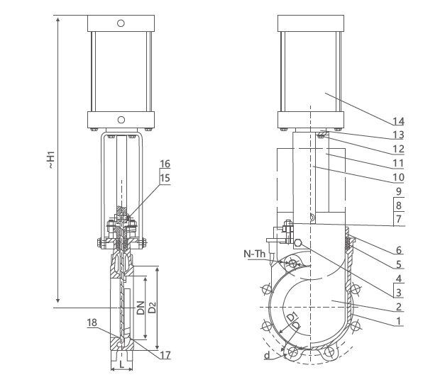

| Nominal diameter DN |
Main Connection Dimension |
| L |
D |
D1 |
D2 |
Do |
N-Th |
d |
H1 |
| 50 |
48 |
165 |
125 |
99 |
180 |
4-M16 |
Φ18 |
460 |
| 65 |
48 |
185 |
145 |
118 |
200 |
4-M16 |
Φ18 |
520 |
| 80 |
51 |
200 |
160 |
132 |
220 |
8-M16 |
Φ18 |
570 |
| 100 |
51 |
220 |
180 |
156 |
240 |
8-M16 |
Φ18 |
680 |
| 125 |
57 |
250 |
210 |
184 |
260 |
8-M16 |
Φ18 |
780 |
| 150 |
57 |
285 |
240 |
212 |
280 |
8-M20 |
Φ23 |
850 |
| 200 |
70 |
340 |
295 |
266 |
300 |
8-M20 |
Φ23 |
980 |
| 250 |
70 |
395 |
350 |
319 |
340 |
12-M20 |
Φ23 |
1140 |
| 300 |
76 |
445 |
400 |
370 |
380 |
12-M20 |
Φ23 |
1360 |
| 350 |
76 |
505 |
460 |
430 |
400 |
16-M20 |
Φ23 |
1460 |
| 400 |
89 |
565 |
515 |
480 |
450 |
16-M24 |
Φ27 |
1630 |
| 450 |
89 |
615 |
565 |
530 |
530 |
20-M24 |
Φ27 |
1770 |
| 500 |
114 |
670 |
620 |
582 |
600 |
20-M24 |
Φ27 |
1960 |
| 600 |
114 |
780 |
725 |
682 |
600 |
20-M27 |
Φ30 |
2245 |
| 700 |
127 |
895 |
840 |
794 |
680 |
24-M27 |
Φ30 |
2600 |
| 800 |
127 |
1015 |
950 |
901 |
680 |
24-M30 |
Φ33 |
2910 |
| 900 |
203(127) |
1115 |
1050 |
1001 |
|
28-M30 |
Φ33 |
3200 |
| 1000 |
216(149) |
1230 |
1160 |
1112 |
|
28-M33 |
Φ36 |
3550 |
| 1200 |
254(156) |
1455 |
1380 |
1328 |
|
32-M36 |
Φ39 |
4250 |
Note: The relative sizes are subject to change depending on different valve torques, mediums and actuator models.
PZ673H (F, X) - Class 150 Overview Dimensions (mm)
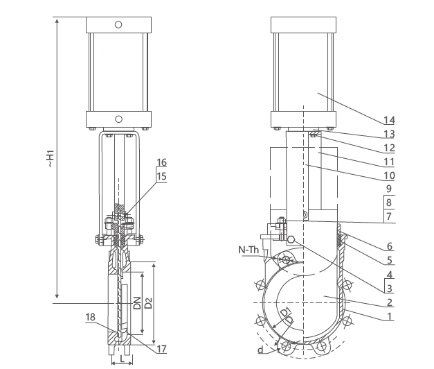
| Nominal diameter DN |
Main Connection Dimension |
| DN |
in |
L |
D |
D1 |
D2 |
Do |
N-Th |
d |
H1 |
| 50 |
2" |
48 |
152 |
120 |
92 |
180 |
4-M5/8-11 |
Φ19 |
460 |
| 65 |
2.5" |
48 |
178 |
139.5 |
105 |
200 |
4-M5/8-11 |
Φ19 |
520 |
| 80 |
3" |
51 |
190.5 |
152.5 |
127 |
220 |
4-M5/8-11 |
Φ19 |
570 |
| 100 |
4" |
51 |
220.5 |
190.5 |
157 |
240 |
8-M5/8-11 |
Φ19 |
680 |
| 125 |
5" |
57 |
254 |
216 |
186 |
260 |
8-M3/4-10 |
Φ22 |
780 |
| 150 |
6" |
57 |
279 |
241.5 |
216 |
280 |
8-M3/4-10 |
Φ22 |
850 |
| 200 |
8" |
70 |
343 |
298.5 |
270 |
300 |
8-M3/4-10 |
Φ22 |
980 |
| 250 |
10" |
70 |
406 |
362 |
324 |
340 |
12-M7/8-9 |
Φ25 |
1140 |
| 300 |
12" |
76 |
483 |
432 |
381 |
380 |
12-M7/8-9 |
Φ25 |
1360 |
| 350 |
14" |
76 |
533 |
476 |
413 |
400 |
12-M1-8 |
Φ29 |
1460 |
| 400 |
16" |
89 |
597 |
539.5 |
470 |
450 |
16-M1-8 |
Φ29 |
1630 |
| 450 |
18" |
89 |
635 |
578 |
533 |
530 |
16-M11/8-7 |
Φ32 |
1770 |
| 500 |
20" |
114 |
699 |
635 |
584 |
600 |
20-M11/8-7 |
Φ32 |
1960 |
| 600 |
24" |
114 |
813 |
749.5 |
691 |
600 |
20-M11/4-7 |
Φ35 |
2245 |
| 750 |
30" |
144 |
984 |
914.5 |
857 |
680 |
28-M11/4-7 |
Φ35 |
2120 |
| 900 |
36" |
203(127) |
1168 |
1086 |
1022 |
680 |
32-M11/2-6 |
Φ41 |
2500 |
| 1000 |
42" |
216(149) |
1346 |
1257.5 |
1193 |
|
36-M11/2-6 |
Φ41 |
2800 |
| 1200 |
48" |
254(156) |
1511 |
1422.5 |
1358 |
|
44-M11/2-6 |
Φ41 |
3300 |
Note: The relative sizes are subject to change in response to different valve torques, mediums and actuator models.