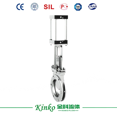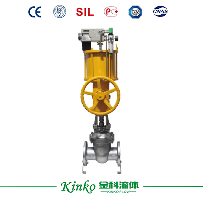
Pneumatic Flange Gate Valve

Pneumatic Flange Gate Valve

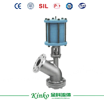
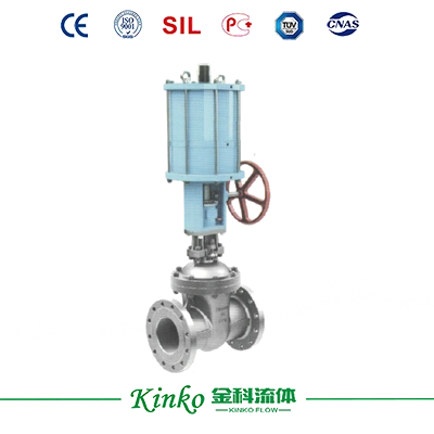
Pneumatic flange gate valve Z641H features double-layer cylinder with buffer mechanism, DN50-800mm, 1.0-4.0MPa, WCB/CF8/CF8M body for reliable industrial pipeline shut-off.
Size
Size
DN50~DN800
Body Material
Body Material
WCB, ZG1Cr18Ni9Ti, ZG1Cr18Ni12Mo2Ti
Mode of Control
Mode of Control
ON/OFF Type, Adjusting Type
Get a Quote
Download Drawings

    Product Overview

    Body Material: Cast Iron, Carbon Steel (WCB), Stainless Steel (CF8, CF8M, CF3, CF3M)

    Seat Material: Metal Sealed (H, Y)

    Mode of Action: Double-acting

    Mode of Control: ON/OFF Type, Adjusting Type

    Annex Choice: Solenoid Valve, POSITIONER, Limit Switch, F.R.L. Manual Gear


    Specifications

    Technique Table


    Design Basis GB Standard ANSI Standard
    Design Standard GB/12234 ANSI B16.34
    Face-to-face dimension Flange connecting GB/12221 ANSI B16.10
    connecting Flange Size GB/9113, JB/T79 ANSI B16.5(2~24")
    ANSI B16.47(28~30")
    Test & inspection JB/T9092 API 598


    Note: The structural length and connecting flange size of the gate valve series can be designed and manufactured as per the user's requirements.


    Form of Main Parts Materials


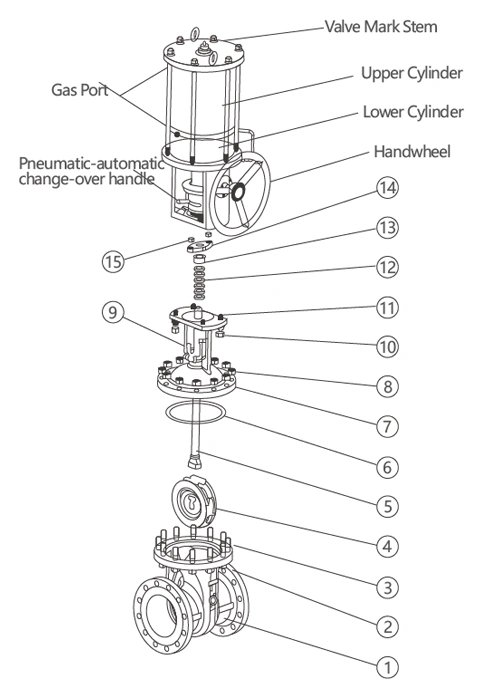
    No. Name of parts Material
    C P R
    1  Body WCB ZG1Cr18Ni9Ti ZG1Cr18Ni12Mo2Ti
    2  Scre Cap 35  304  304 
    3  Screw 35  304  304 
    4  Shut-off Device WCB ZG1Cr18Ni9Ti ZG1Cr18Ni12Mo2Ti
    5  Sem 1Cr13 1Cr18Ni9Ti 1Cr18Ni12Mo2Ti
    6  Gasket PTFE, Stainless Steel+Graphite, PTFE
    7  Cover WCB ZG1Cr18Ni9Ti ZG1Cr18Ni12Mo2Ti
    8  Scre Cap 35  304  304 
    9  Lifting Ring Screw 35  304  304 
    10  Scre Cap 35  304  304 
    11  Screw 35  304  304 
    12  Packing PTFE, Graphite, PTFE
    13  Packing Gland WCB 1Cr18Ni9Ti 1Cr18Ni12Mo2Ti
    14  Packing Plate WCB 1Cr18Ni9Ti 1Cr18Ni12Mo2Ti
    15  Scre Cap 35  304  304 


    Note: The main spare parts and sealed seat material of the gate valve series can be designed as options as per users' special requirements.


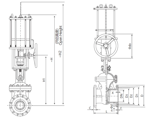
    Z6S41 (0) H (Y)-PN16 (1.6MPa) Overview Dimension (mm)


    Nominal diameter DN Outline Dimension Connecting Size
    L H H1 H2 Φdo D D1 D2 C f n-Φd
    50 250 790 420 840 180 165 125 99 18 3 4-Φ18
    65 265 830 440 920 180 180 145 120 18 3 4-Φ18
    80 280 910 460 990 200 200 160 132 20 3 8-Φ18
    100 300 1050 560 1150 250 220 180 156 22 3 8-Φ18
    125 325 1170 620 1270 280 245 210 185 22 3 8-Φ18
    150 350 1240 660 1390 320 285 240 211 24 3 8-Φ22
    200 400 1520 810 1720 400 340 295 266 24 3 12-Φ22
    250 450 1700 930 1950 400 405 355 319 26 3 12-Φ26
    300 500 1930 1090 2230 450 460 410 370 28 4 12-Φ26
    350 550 2160 1230 2510 450 520 470 429 30 4 16-Φ26
    400 600 2330 1360 2730 500 580 525 480 32 4 16-Φ30
    450 650 2540 1510 2990 500 640 585 548 34 4 20-Φ30
    500 700 2750 1660 3250 550 715 650 609 36 4 20-Φ33
    600 800 3080 1910 3680 550 840 770 720 38 5 20-Φ36
    700 900 3570 2200 4270 600 910 840 794 40 5 24-Φ36


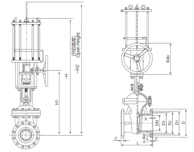
    Z6S41(0)H(Y)-Class150 Overview Dimension (mm)


    Nominal diameter DN Main Connection Dimension Connecting Size
    DN in L H H1 H2 Φdo D D1 D2 C f n-Φd
    50 2 173 790 420 840 180 152 120.5 92 16 2 4-Φ19
    65 2 1/2 190 860 440 920 180 178 139.6 105 18 2 4-Φ19
    80 3 203 910 460 990 200 190 152.5 127 19 2 4-Φ19
    100 4 229 1050 560 1150 250 229 190.5 157 24 2 8-Φ19
    125 5 254 1172 620 1270 280 254 216 186 24 2 8-Φ22
    150 6 267 1240 660 1390 320 279 241.5 216 26 2 8-Φ22
    200 8 292 1520 810 1720 400 343 298.5 270 29 2 8-Φ22
    250 10 330 1700 930 1950 400 406 362 324 31 2 12-Φ25
    300 12 256 1930 1090 2230 450 483 432 381 32 2 12-Φ25
    350 14 381 2160 1230 2510 450 533 476 413 35 2 12-Φ29
    400 16 406 2330 1360 2730 500 597 540 470 37 2 16-Φ29
    450 18 432 2540 1510 2990 500 635 578 533 40 2 16-Φ32
    500 20 457 2750 1660 3250 550 699 635 584 43 2 20-Φ32
    600 24 508 3080 1910 3680 550 813 749.5 692 48 2 20-Φ35
    700 28 610 3570 2200 4270 600 947 863.6 800 45 2 28-Φ35

    Downloads

    PDF file icon
    Fluid Control 2026

    Application & Case

    Lorem ipsum dolor sit amet, consectetur adipiscing elit. Aenean euismod bibendum laoreet. Proin gravida dolor sit amet lacus accumsan et viverra justo commodo. Proin sodales pulvinar sic tempor. Sociis natoque penatibus et magnis dis parturient montes, nascetur ridiculus mus. Nam fermentum, nulla luctus pharetra vulputate, felis tellus mollis orci, sed rhoncus pronin sapien nunc accuan eget.

    Discover Our Precision Cleaning Solutions Arrow icon
    Industrial application case study

    Related Recommended Products

    Discover Our Range of Products Built for Your Industry's Challenges
    Contact Us

    Get Technical Support or a Customized Solution

    Do our standard products not meet your needs? Share your operating parameters with us, and the Jinke technical team will provide you with personalized selection recommendations and a customized solution.
    Contact experts
    News & Blog
    The Working Principle of The Regulating Valve
    The Working Principle of The Regulating Valve
    The regulating valve is a key piece of equipment used to accurately control the flow of fluids (gas, liquids, or steam) ...
    2026.09.03
    Learn more
    How to install a straight stroke pneumatic actuator?
    How to install a straight stroke pneumatic actuator?
    The installation of straight-stroke pneumatic actuators should follow strict steps and precautions to ensure their effic...
    2026.08.12
    Learn more
    Introduction To The Stroke and Control Mode of Electric Actuators
    Introduction To The Stroke and Control Mode of Electric Actuators
    According to the movement form, the electric actuator can be divided into straight stroke, angular stroke and multi-turn...
    2026.08.05
    Learn more
    onlineCONTACT
    We value your privacy
    We use cookies to provide you with a better online experience, analyse and measure website usage, and assist in our marketing efforts.
    Accept All
    Don't Accept