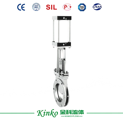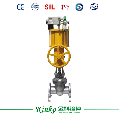
Pneumatic Gate Valve

Pneumatic Gate Valve

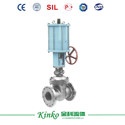
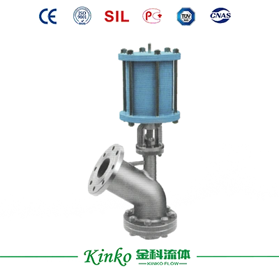
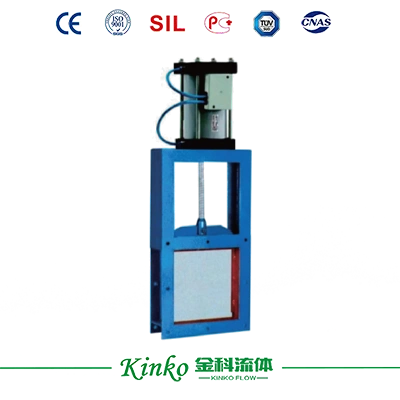
The structure is simple, the operation is flexible, the weight is light, there is no obstruction, and the cutting is fast. It is particularly suitable for the transportation and flow adjustment of various non-viscous solids, powders, and particles smaller than 10mm.
Size
Size
200*200-1000*1000
Body Material
Body Material
Carbon Steel, Stainless Steel
Ambient Temperature
Ambient Temperature
-10~+200 ℃
Get a Quote
Download Drawings

    Product Overview

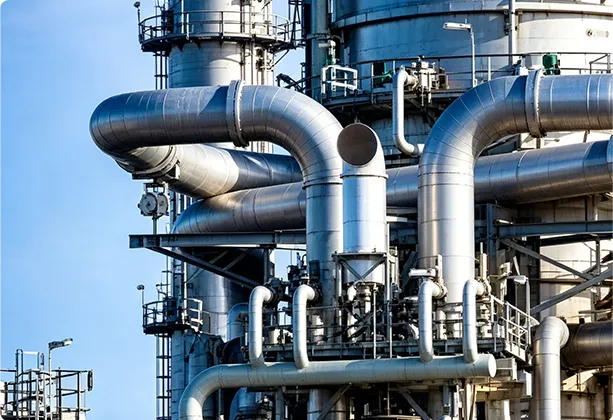
    The installation is not limited by angles; the operation is convenient, and the opening can be adjusted at any time. Used for the top, bottom, and import/export of warehouses in industries such as building materials, metallurgy, mining, electricity, chemical, glass, light industry, and grain. It is an ideal device for controlling large flow changes, frequent startups, and rapid shutdowns.


    upload/1c/202609/Z673X-2.webp

    Specifications

    Technical Parameters


    Nominal diameter DN (mm) 200*200-1000*1000
    Nominal pressure (MPa) 1.0
    Main components Valve body Carbon steel and stainless steel
    Seal ring Hard seal, soft seal
    Filler flexible graphite
    Applicable working conditions Applicable medium Blast furnace gas ash, dry ash, coal powder, dust, cement, granular materials, and other media
    Applicable temperature -10~+200 ℃
    Actuator Single-acting Equipped with a reset cylindrical spring and automatic reset function upon gas loss
    Double-acting It has greater thrust than a single-acting cylinder of the same diameter, but does not have an automatic reset function
    Optional Accessories Electromagnetic valve, limit switch, filter pressure reducing valve, manual mechanism


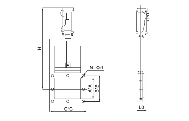
    Main dimensions and connection dimensions (mm)


    Nominal diameter DN Main Connection Dimension
    L0 A*A B*B C*C H N-Φd
    One-way 100 200*200 256*256 296*296 820 8-Φ12
    100 250*250 306*306 346*346 930 8-Φ14
    100 300*300 356*356 396*396 1050 8-Φ14
    100 400*400 456*456 496*496 1140 12-Φ14
    120 450*450 510*510 556*556 1450 12-Φ18
    120 500*500 560*560 606*606 1610 16-Φ18
    Bidirectional 120 600*600 660*660 706*706 1830 16-Φ18
    140 700*700 770*770 820*820 2130 20-Φ18
    140 800*800 870*870 920*920 2440 20-Φ18
    160 900*900 974*974 1030*1030 2660 27-Φ23
    160 1000*1000 1074*1074 1130*1130 2870 27-Φ23

    Downloads

    PDF file icon
    Fluid Control 2026

    Application & Case

    Lorem ipsum dolor sit amet, consectetur adipiscing elit. Aenean euismod bibendum laoreet. Proin gravida dolor sit amet lacus accumsan et viverra justo commodo. Proin sodales pulvinar sic tempor. Sociis natoque penatibus et magnis dis parturient montes, nascetur ridiculus mus. Nam fermentum, nulla luctus pharetra vulputate, felis tellus mollis orci, sed rhoncus pronin sapien nunc accuan eget.

    Discover Our Precision Cleaning Solutions Arrow icon
    Industrial application case study

    Related Recommended Products

    Discover Our Range of Products Built for Your Industry's Challenges
    Contact Us

    Get Technical Support or a Customized Solution

    Do our standard products not meet your needs? Share your operating parameters with us, and the Jinke technical team will provide you with personalized selection recommendations and a customized solution.
    Contact experts
    News & Blog
    The Working Principle of The Regulating Valve
    The Working Principle of The Regulating Valve
    The regulating valve is a key piece of equipment used to accurately control the flow of fluids (gas, liquids, or steam) ...
    2026.09.03
    Learn more
    How to install a straight stroke pneumatic actuator?
    How to install a straight stroke pneumatic actuator?
    The installation of straight-stroke pneumatic actuators should follow strict steps and precautions to ensure their effic...
    2026.08.12
    Learn more
    Introduction To The Stroke and Control Mode of Electric Actuators
    Introduction To The Stroke and Control Mode of Electric Actuators
    According to the movement form, the electric actuator can be divided into straight stroke, angular stroke and multi-turn...
    2026.08.05
    Learn more
    onlineCONTACT
    We value your privacy
    We use cookies to provide you with a better online experience, analyse and measure website usage, and assist in our marketing efforts.
    Accept All
    Don't Accept